
Induction cooker air channel structure and induction cooker
An induction cooker and air duct technology, which is applied to the structural parts of electrical equipment, electrical components, household stoves/stoves, etc. Simple, solve the effect of unsatisfactory cooling effect
Patent Information
- Authority / Receiving Office
- CN · China
- Patent Type
- Applications(China)
- Current Assignee / Owner
- Publication Date
- 2016-10-26
Smart Images
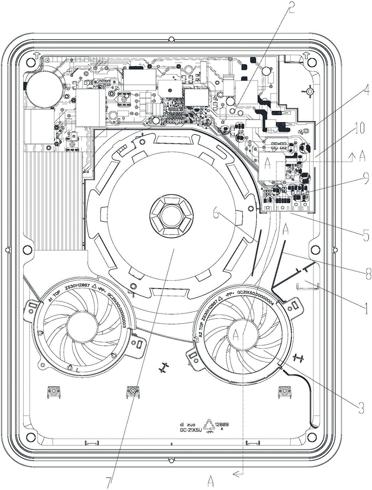
Figure 1 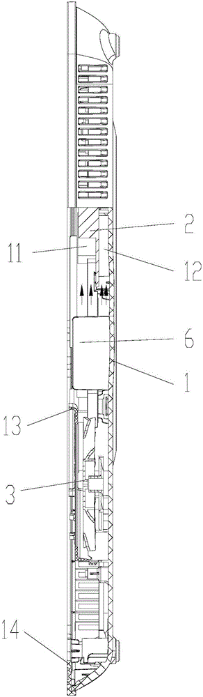
Figure 2 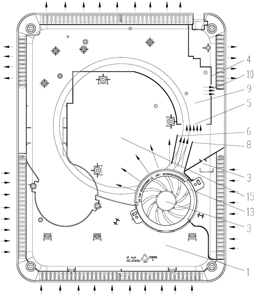
Figure 3
Abstract
Description
technical field
[0001] The invention relates to the field of household appliances, in particular to the field of induction cookers, in particular to an induction cooker air duct structure and an induction cooker. Background technique
[0002] The induction cooker mainly uses the alternating magnetic field generated by the electromagnetic coil for heating. In order to generate an alternating magnetic field, a high-frequency alternating current needs to be passed into the electromagnetic coil, which requires switching elements such as IGBTs to control the current flowing into the electromagnetic coil. In this way, components such as IGBT and electromagnetic coil will generate high heat, so it is necessary to design a corresponding heat dissipation structure on the induction cooker.
[0003] At present, the mainstream ultra-thin induction cooker on the market, due to the thinner thickness, the air inlet and outlet space becomes smaller, and the ultra-thin induction cooker uses...
Examples
Embodiment Construction
[0026] The embodiments of the present invention will be described in detail below with reference to the accompanying drawings, but the present invention can be implemented in many different ways defined and covered by the claims.
[0027] The invention provides an induction cooker air channel structure, which is especially suitable for use in an ultra-thin induction cooker, which can not only achieve the purpose of energy saving, but also greatly reduce the problem of temperature rise of electronic components on the main board.
[0028] Please refer to Figure 1 to Figure 8 , the main board 2 is installed on the base 1, in order to realize the heat dissipation and cooling of the upper layer 11 and the lower layer 12 of the main board 2, a fan 3 is arranged on the outside of the main board 2, wherein, the gap between the main board 2 and the base 1 is provided with a surrounding The ribs 4 and surrounding ribs 4 are arranged around the circumference of the main board 2 . Where...