
A voltage equalization method for the main grounding grid of a substation
A substation grounding grid and grounding grid technology, which is applied in the direction of measuring electricity, measuring electrical variables, measuring resistance/reactance/impedance, etc., can solve the problems of rarely setting up living areas and uneven distribution of ground potential, and achieves reduction of contact voltage and improvement of Safe, less unevenly distributed effects
Patent Information
- Authority / Receiving Office
- CN · China
- Patent Type
- Patents(China)
- Current Assignee / Owner
- Publication Date
- 2019-01-18
Smart Images
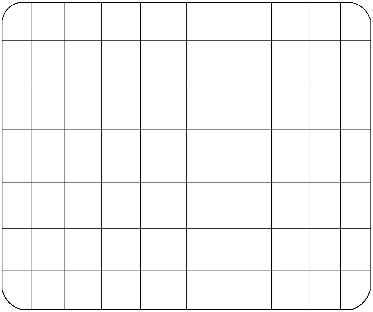
Figure 1 
Figure 2 
Figure 3
Abstract
Description
technical field
[0001] The invention relates to the technical field of a voltage equalization method for a grounding grid, in particular to a voltage equalization method for a main grounding grid of a substation. Background technique
[0002] A good grounding system is a necessary condition to ensure the safe operation of substations. According to relevant domestic grounding standards, the power frequency grounding resistance of the substation grounding grid should meet Among them, I is the grounding current flowing into the grounding grid. When the grounding resistance of the main grounding network satisfies this formula, the ground potential rise of the substation will not exceed 2kV, which can generally guarantee the safety of equipment and personal.
[0003] With the development of economy and society, the scale of power system is expanding day by day, and the ground fault current of voltage busbars at all levels in substations is increasing year by year. When a sing...
Examples
Embodiment Construction
[0038] Such as figure 1 As shown, it is the grounding grid of a typical substation, the size of the grounding grid is 60m×50m, and the buried depth is 0.8m. Since the substation uses multiple horizontal grounding bodies to form a grid-like pressure equalization zone, although the ground potential distribution in the middle of the grounding grid fluctuates, the fluctuation is not large; In the junction zone, the ground current will flow into the ground through the ground grid, causing drastic ground potential changes here, such as Figure 8 , Figure 9 As shown, the contact voltage and step voltage are greatly increased, which affects the safety of the grounding grid.
[0039] Since all the ground current needs to flow out through the edge of the ground grid, the potential distribution at the corners of the ground grid is extremely uneven. How to reasonably increase the contact area between the corners of the ground grid and the soil to increase the flow of the ground current...