
Tension-resisting anti- beam-falling combined shock insulation device and construction method thereof
A technology of anti-falling beams and shock isolation, applied in the direction of bridges, bridge parts, bridge materials, etc., can solve the problems of substructure damage, brittle damage of stoppers, uneconomical design, etc., to prevent falling beams, simple structure, good vertical effect on tensile strength
Patent Information
- Authority / Receiving Office
- CN · China
- Patent Type
- Applications(China)
- Current Assignee / Owner
- Publication Date
- 2017-05-10
Smart Images
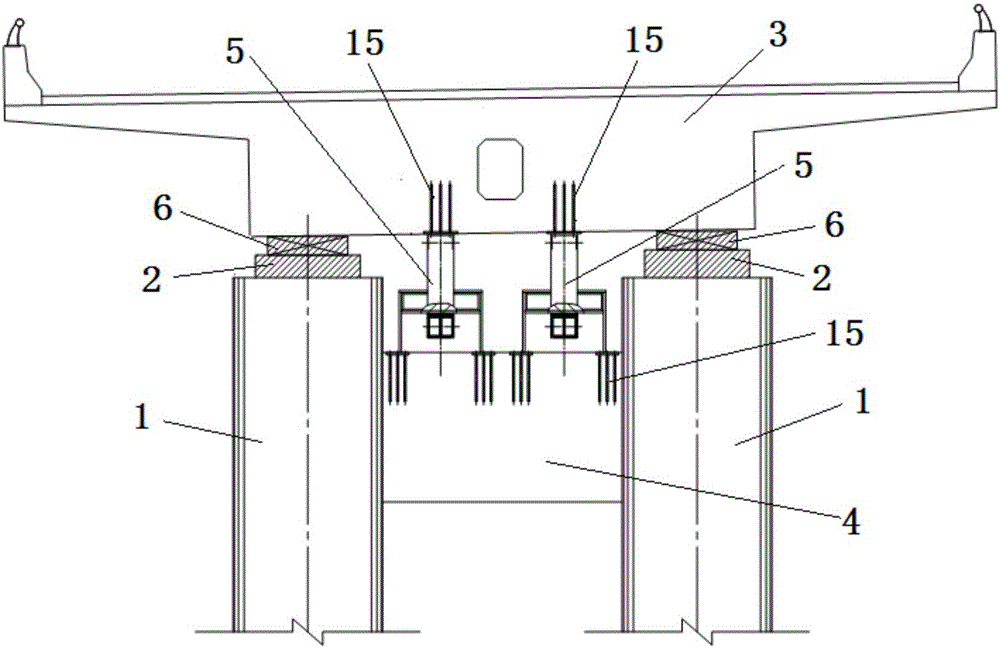
Figure 1 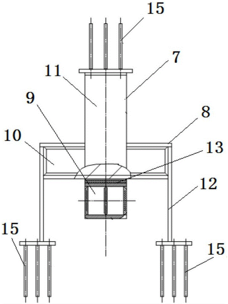
Figure 2 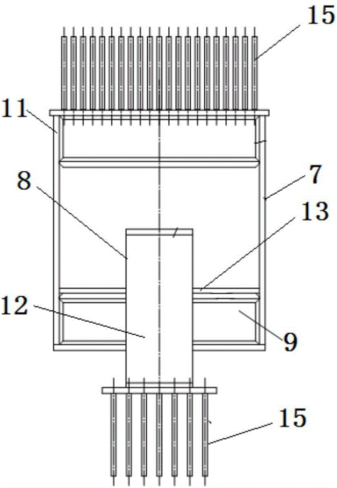
Figure 3
Abstract
Description
technical field
[0001] The invention relates to a shock-isolation device, in particular to a combined shock-isolation device of tensile anti-drop beams and a construction method thereof. Background technique
[0002] One of the warnings of the Wenchuan Earthquake is that we should pay close attention to the research and application of bridge shock absorption and isolation technology. The seismic isolation measures widely used in the bridge field are lead rubber isolation bearings. The support is made of rubber sheets and thin steel plates alternately laminated and then vulcanized, and filled with lead rods. Among them, the role of the thin steel plate is to restrain the lateral deformation of the rubber sheet, so that the rubber bearing has the same vertical stiffness as the conventional component. The role of the rubber sheet is to provide the required horizontal displacement and reduce the horizontal stiffness. The shock absorption and isolation mechanism of the lead ru...
Examples
Embodiment Construction
[0031] The implementation of the present invention will be described in detail below in conjunction with the accompanying drawings, but it does not constitute a limitation of the present invention, and is only used as an example. At the same time, the advantages of the present invention will become clearer and easier to understand through the description.
[0032] Such as figure 1 Shown: a combined shock-isolation device for tensile anti-fall beams, characterized in that it includes a lead rubber shock-isolation support 6 for horizontal anti-fall beams and an anti-pullout device 5 for vertical anti-pullout, The lead-core rubber shock-isolation bearing 6 is connected between the pier 1 and the main girder 3, one end of the anti-pullout device 5 is fixed on the lower surface of the main girder 3, and the other end of the anti-pullout device 5 is fixed on the top of the tie beam 4 On the other hand, the anti-pullout device 5 includes an upper U-shaped steel member 7 and a lower ...