
Novel connecting rod efficient reduction box
A reducer and connecting rod technology, applied in mechanical equipment, transmission parts, belts/chains/gears, etc., can solve the problems of poor reducer strength and poor control effect, and achieve the elimination of noise pollution and rapid dripping. , good effect
Patent Information
- Authority / Receiving Office
- CN · China
- Patent Type
- Applications(China)
- Current Assignee / Owner
- Publication Date
- 2017-07-25
- Estimated Expiration
- Not applicable · inactive patent
Smart Images
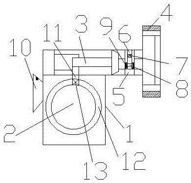
Figure 1
Abstract
Description
technical field
[0001] The invention relates to a reducer, in particular to a novel connecting rod high-efficiency reducer. Background technique
[0002] The reducer is an independent closed transmission device between the prime mover and the working machine. It is used to reduce the speed and increase the torque to meet the work needs. The selection of the reducer should be based on the selection conditions of the working machine, technical parameters, and the power machine Performance, economy and other factors, compare the outer dimensions, transmission efficiency, carrying capacity, quality, price, etc. of different types and varieties of reducers, and choose the most suitable reducer. The reducer is a relatively precise machine. Stable conveying efficiency is required at times, and some reducers are not strong enough when in use, and the control effect is not good when working. Contents of the invention
[0003] The purpose of the present invention is to provide a ne...
Examples
Embodiment Construction
[0012] The present invention will be further described below in conjunction with the accompanying drawings.
[0013] A new type of connecting rod high-efficiency reducer, including a case 1, a connecting rod 2 is arranged in the case 1, an output shaft 3 is provided between the connecting rod 2 and the case 1, and an output flange 4 is connected next to the output shaft 3. In the output method A sealing device 5 is provided between the flange 4 and the output shaft 2. The sealing device 5 is an inverted M-shaped structure. The sealing device 5 is provided with an oil filling port 6, and the oil filling port 6 is provided with a dispersing part 7, wherein the dispersing part is a fine mesh structure. The lower part of the sealing device 5 is connected with an oil seal 8, and oil seal end caps 9 are arranged on both sides of the oil seal 8, and the left and right symmetrical oil seal end caps 9 clamp the oil seal 8, the oil seal 8 is a U-shaped structure, and the oil seal 8 commu...