
Hair drier
A rack and motor technology, applied in hairdressing equipment, hair drying devices, hair washing or scalp washing devices, etc., can solve the problems of messy placement, inconvenient access, fixed and non-adjustable height of hair dryer, etc., and achieve high Automatic adjustment, simple structure, convenient placement and access
Patent Information
- Authority / Receiving Office
- CN · China
- Current Assignee / Owner
- Publication Date
- 2017-08-29
- Estimated Expiration
- Not applicable · inactive patent
Smart Images
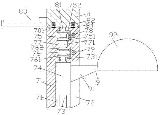
Figure 1 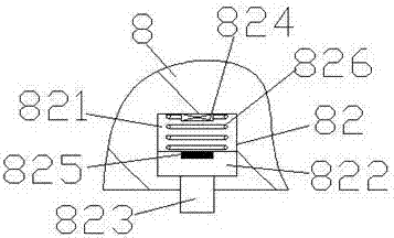
Figure 2 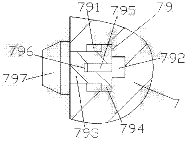
Figure 3
Abstract
Description
technical field
[0001] The invention relates to the field of hairdressing tools, in particular to a hair drying machine. Background technique
[0002] All hair salons need to be equipped with hair dryers to heat and shape customers’ hair. The height of traditional hair dryers is fixed and cannot be adjusted, while some height-adjustable hair dryers are manually adjusted through adjustable lift tubes, and automatic adjustment has not yet been realized. and need to use many large and small various hairdressing tools in the hairdressing process, the operator generally needs to place the tools on the hairdressing platform in front of the mirror, which is messy and inconvenient to use. Contents of the invention
[0003] The technical problem to be solved by the present invention is to provide a hair drying machine, which can solve the above-mentioned problems in the prior art.
[0004] The present invention is achieved through the following technical solutions: a drying machin...
Examples
Embodiment Construction
[0021] Such as Figure 1-Figure 4 As shown, a hair drying machine of the present invention includes a frame 7, a rotating seat 8 arranged above the frame 7, and a drying part 9 composed of a support rod 91 and a heating cover 92. The frame 7 There is a downwardly extending first sliding chamber 71 inside, a sliding chamber 72 arranged along the first sliding chamber 71 is provided on the right side of the first sliding chamber 71, and a spiral Threaded rod 73, on the threaded threaded rod 73, a sliding block 74 is connected with rotation fit, and the right side end surface of the sliding block 74 is fixedly connected with the support rod 91, and the frame above the first sliding chamber 71 7 is provided with a first empty slot 75 and a second empty slot 76, an isolation plate 77 is provided between the first empty slot 75 and the second empty slot 76, and a second empty slot 75 is provided in the first empty slot 75. Two cone wheels 752 and the first cone wheel 751, the fourt...