
A Multistage Axial Flow Compressor with Rotor-Stator Combined with Self-Adaptive Adjustment
A self-adapting, axial-flow compressor technology, applied in axial-flow pumps, mechanical equipment, machines/engines, etc., can solve the problems of inability to form circumferentially uniform jets, limited working conditions, and strong inverse pressure gradients.
Patent Information
- Authority / Receiving Office
- CN · China
- Patent Type
- Patents(China)
- Current Assignee / Owner
- Publication Date
- 2021-02-09
Smart Images
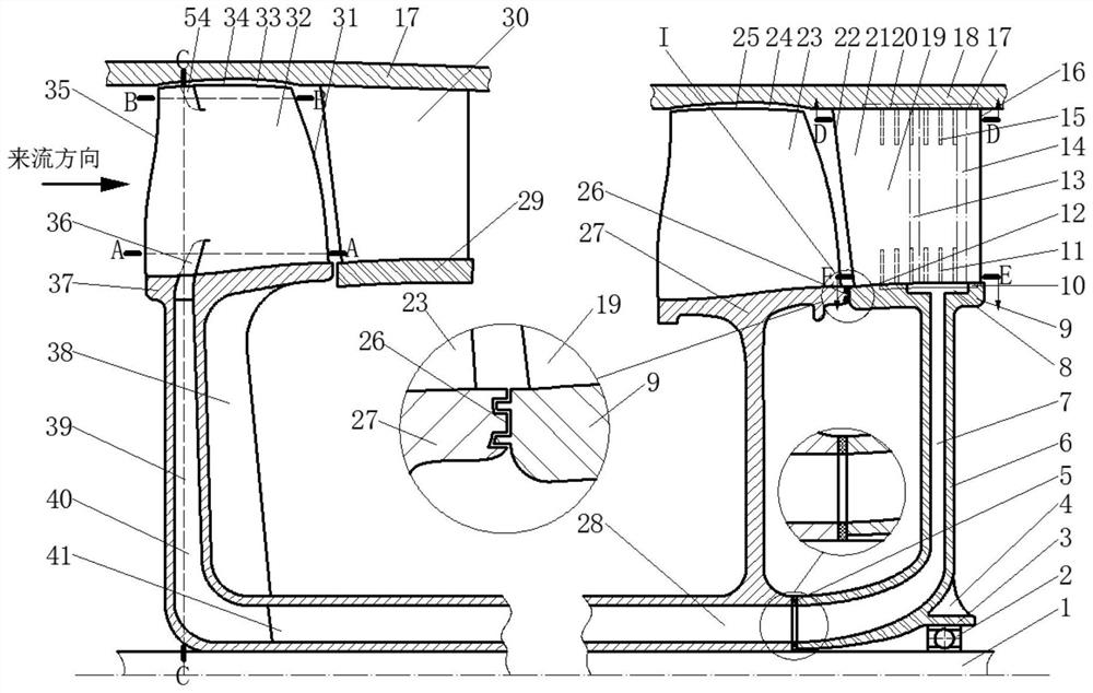
Figure 1 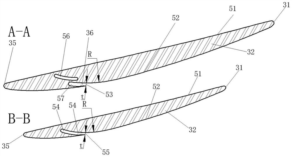
Figure 2 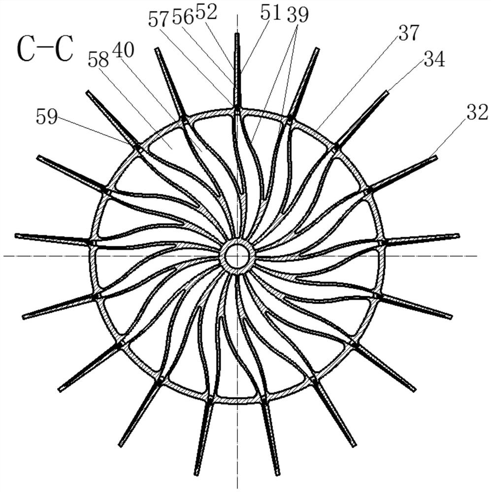
Figure 3
Abstract
Description
technical field
[0001] The invention relates to the field of multi-stage axial-flow compressors, in particular to a multi-stage axial-flow compressor with rotor-stator blades combined with self-adaptive adjustment. Background technique
[0002] The compressor is the core component of the aviation gas turbine engine. It is composed of multi-stage rotors and stators arranged in a staggered order. Its function is to increase the gas pressure rise; in the flow inside the compressor, due to the small flow space, the reverse pressure of the fluid The gradient effect is strong, and it has a complex vortex structure; the corner separation structure located at the stator end zone and the leakage flow structure located at the rotor tip are the main secondary flow structures inside the compressor, and are the main causes of flow loss and blockage inside the compressor. The source has a vital impact on the performance of the compressor's pressure ratio, efficiency, and margin. In severe...
Examples
Embodiment 1
[0027] like figure 1 As shown, the multistage axial flow compressor of the present invention includes target rotor blades 32, downstream stator blades 19, downstream stator blade discs 6, target rotor blade discs 37, and a rotor disc drainage chamber that rotates synchronously with the engine shaft 1 28 structure; there is a blade tip gap 33 between the target rotor blade 32 and the casing 18, which is connected to the engine shaft 1 through the target rotor blade disc 37 with a jet gas guide cavity 40; there is no gap between the downstream stator blade 19 and the casing 18 Seam connection, with casing end wall 20 structure; seamless connection between downstream stator blade 19 and downstream stator blade hub 9, with hub end wall 12 structure; downstream stator blade disc 6 is stationary relative to casing 18, passes through downstream stator blade wheel The disc bearing 2 is connected to the engine shaft 1, and is connected to the target rotor blade disc 37 through the seal...
Embodiment 2
[0032] like Figure 6 As shown, this embodiment is basically the same as Embodiment 1, except that the downstream stator with the suction slot is immediately downstream of the target rotor blade, and there is no blade row structure between them.