
Clamp for machining small batch of tee workpieces
A small batch, workpiece technology, applied in the field of parts processing, can solve problems affecting the efficiency of processing, achieve the effect of expanding the processing range and ensuring shape and position tolerances
Patent Information
- Authority / Receiving Office
- CN · China
- Patent Type
- Applications(China)
- Current Assignee / Owner
- Publication Date
- 2017-09-22
Smart Images
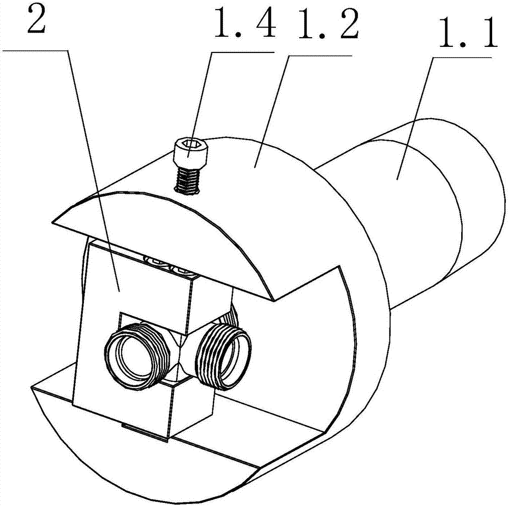
Figure 1 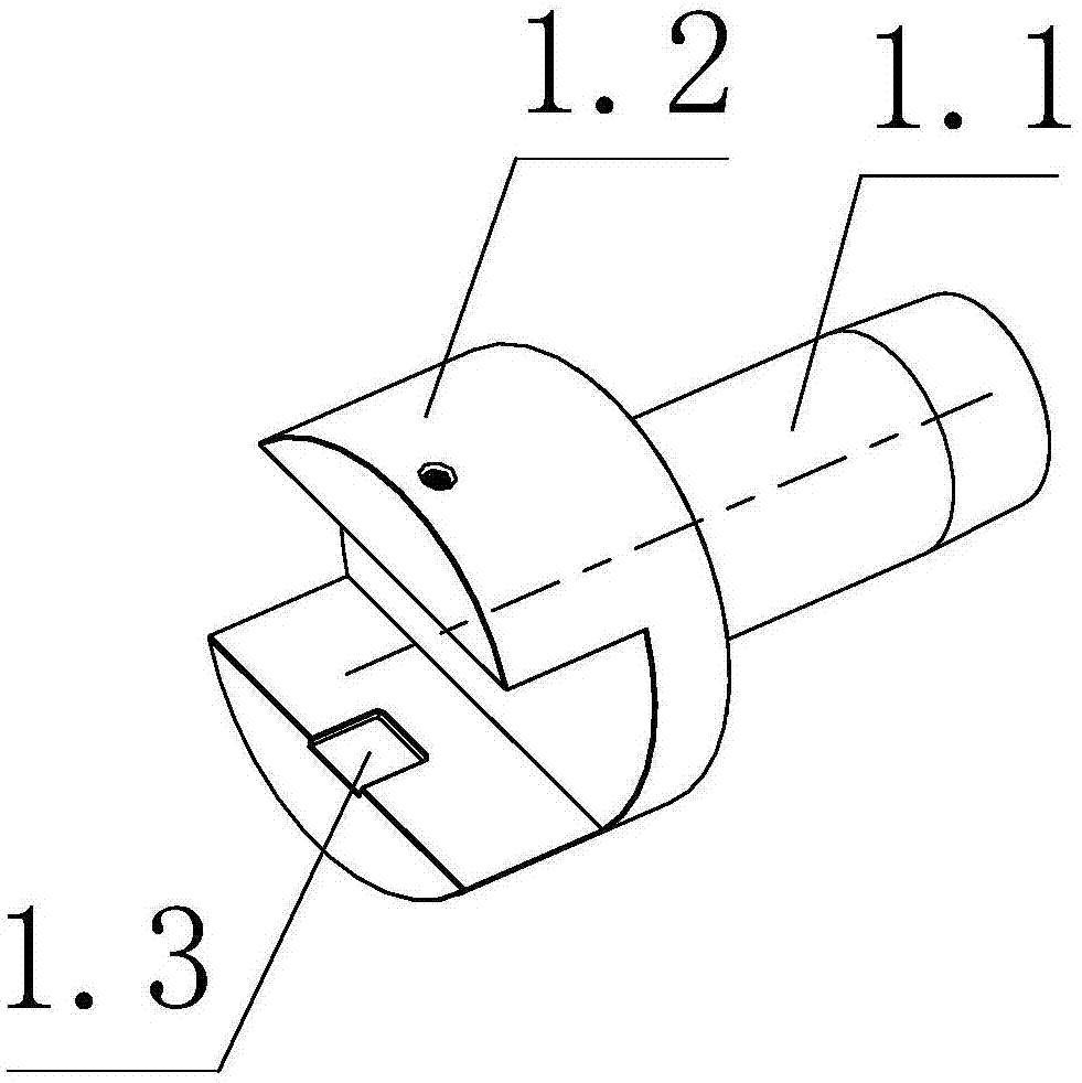
Figure 2 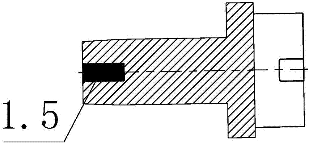
Figure 3
Abstract
Description
technical field
[0001] The invention relates to the technical field of part processing, in particular to a fixture for processing three-way workpieces in small batches. Background technique
[0002] Processing three-way workpieces has always been a difficult problem in turning. The commonly used method is to align individually on the four-jaw chuck and process each end face. This method leads to the accuracy or shape tolerance of the processed workpiece depends on the operator of the equipment, and the processing quality cannot be guaranteed. In the case of large-scale production of three-way workpieces, the turning equipment will be modified to equip the equipment with hydraulic or pneumatic indexing chucks, so that after one end is processed, the indexing chuck can be directly indexed, and the conversion needs to process three-way The end face of the workpiece, this mass production method can guarantee the shape and position tolerance of the three-way workpiece. But when...
Examples
Embodiment Construction
[0023] In order to make the content of the present invention more clearly understood, the present invention will be further described in detail below based on specific embodiments and in conjunction with the accompanying drawings.
[0024] such as 1 and Figure 5 A fixture for processing three-way workpieces in small batches is shown, which includes a fixture body 1 and a holder 2. The fixture body 1 includes a first body 1.1 and a second body 1.2 coaxially arranged. The first body 1.1 and the second body 1.2 are coaxially arranged. The inner hole of the main shaft of the lathe is close to the axial direction, the first body 1.1 and the second body 1.2 are in the shape of a cylinder, the diameter of the second body 1.2 is larger than the diameter of the first body 1.1, and the end of the second body 1.2 is recessed inward. There is a space for holding the holder 2, a groove 1.3 is provided in the center of the bottom surface of the space for holding the holder 2, and a screw 1...