
Steam trap valve for tire vulcanizing machine
A tire vulcanization and steam trap technology, applied in steam traps, mechanical equipment, etc., can solve the problems of unstable sealing performance, poor working reliability, steam leakage, etc., and achieve rapid and accurate opening and closing, stable working performance and reasonable structure. advanced effects
Patent Information
- Authority / Receiving Office
- CN · China
- Patent Type
- Applications(China)
- Current Assignee / Owner
- Publication Date
- 2017-10-03
Smart Images
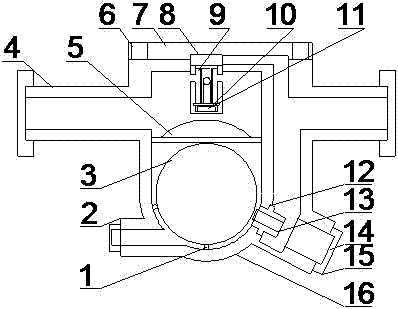
Figure 1 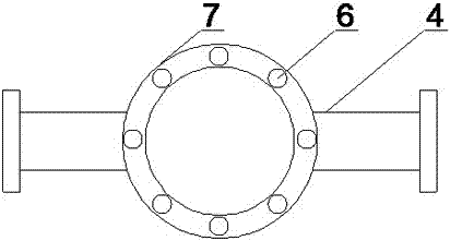
Figure 2
Abstract
Description
technical field
[0001] The invention relates to the field of tire manufacturing, in particular to a steam trap for a tire vulcanizer. Background technique
[0002] The normal operation of the steam trap greatly affects the performance and efficiency of the vulcanizing machine in the tire manufacturing process. At the same time, it also affects the service life of the equipment, and sometimes brings unexpected vicious accidents, causing huge losses to the enterprise. Therefore, it is very important to choose a good trap.
[0003] In the existing free float trap, under actual working conditions, the medium in the valve cavity is a two-phase mixture of high-temperature steam and high-temperature condensed water, and its dynamic changes make the float unstable, and the trap will be in a state of being open. In the seemingly closed state, the opening and closing action of the trap is not obvious, and the steam (gas) leakage of the trap is relatively large, which has the problem...
Examples
Embodiment Construction
[0017] The following will clearly and completely describe the technical solutions in the embodiments of the present invention with reference to the accompanying drawings in the embodiments of the present invention. Obviously, the described embodiments are only some, not all, embodiments of the present invention. Based on the embodiments of the present invention, all other embodiments obtained by persons of ordinary skill in the art without making creative efforts belong to the protection scope of the present invention.
[0018] see Figure 1-2 , the present invention provides a technical solution: a steam trap for a tire vulcanizer, comprising a valve body 16, a main valve seat 15 and an auxiliary valve body 8, the main valve seat 15 is arranged through the lower right part of the valve body 16, and the auxiliary valve body 8 Set at the upper center of the valve body 16, the top of the valve body 16 is fixed with a bonnet 7, and the sub-valve body 8 is welded under the bonnet ...