
Engine hood of passenger car
A technology for hoods and passenger cars, which is applied to power units, vehicle components, and the arrangement of cooling combination of power units, etc., can solve the problems of low heat dissipation efficiency and weak controllability, and achieve high heat dissipation efficiency, strong controllability, and improved heat dissipation efficiency effect
Patent Information
- Authority / Receiving Office
- CN · China
- Current Assignee / Owner
- Publication Date
- 2017-12-05
- Estimated Expiration
- Not applicable · inactive patent
Smart Images
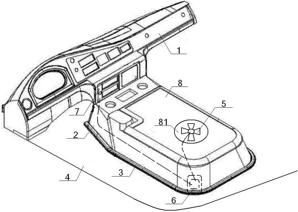
Figure 1 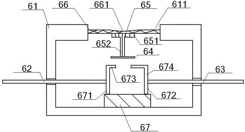
Figure 2
Abstract
Description
technical field
[0001] The invention relates to an engine device, in particular to a passenger car engine cover, which is particularly suitable for improving heat dissipation efficiency and enhancing controllability. Background technique
[0002] At present, the engine covers of existing motor vehicles, such as cars, passenger cars or special vehicles, are basically closed structures, lacking heat dissipation design, and the heat generated by the engine needs to be dissipated through the heat dissipation port of the front of the vehicle, and the heat dissipation effect is poor.
[0003] Chinese patent, the authorized announcement number is CN202439763Y, and the authorized announcement date is September 19, 2012. The utility model patent discloses an engine cover plate with good heat dissipation performance, including the cover plate body, and a ventilation system is provided on the cover plate body. Holes, a heat dissipation ventilation hood is provided on the ventilation ho...
Examples
Embodiment Construction
[0019] The present invention will be described in further detail below in conjunction with the accompanying drawings and specific embodiments.
[0020] see figure 1 – figure 2 , a passenger car engine cover, comprising a top cover 8, a base 2 and a damping strip 3, the top of the base 2 is provided with a top cover 8, and the bottom edge of the base 2 is connected to the floor 4 through the damping strip 3, and The front end of the base 2 is connected with the instrument assembly 1;
[0021] The top cover 8 is provided with a cooling hole 81, the cooling fan 5 is arranged in the cooling hole 81, and the cooling fan 5 is connected with the power supply 7 circuit after the controller 6, and the controller 6 is arranged on the base 2 away from the instrument One end of the assembly 1, the power supply 7 is set on the base 2 near the end of the instrument assembly 1;
[0022] Described controller 6 comprises metal casing 61, input power line 62, output power line 63, energizin...