
Novel marine propeller for speed increasing
A technology for marine propellers and propellers, which is applied in the direction of rotating propellers, ship propulsion, ship parts, etc., to achieve the effects of erosion improvement, safety protection, and improvement of propulsion efficiency
Patent Information
- Authority / Receiving Office
- CN · China
- Current Assignee / Owner
- Publication Date
- 2018-04-13
Smart Images
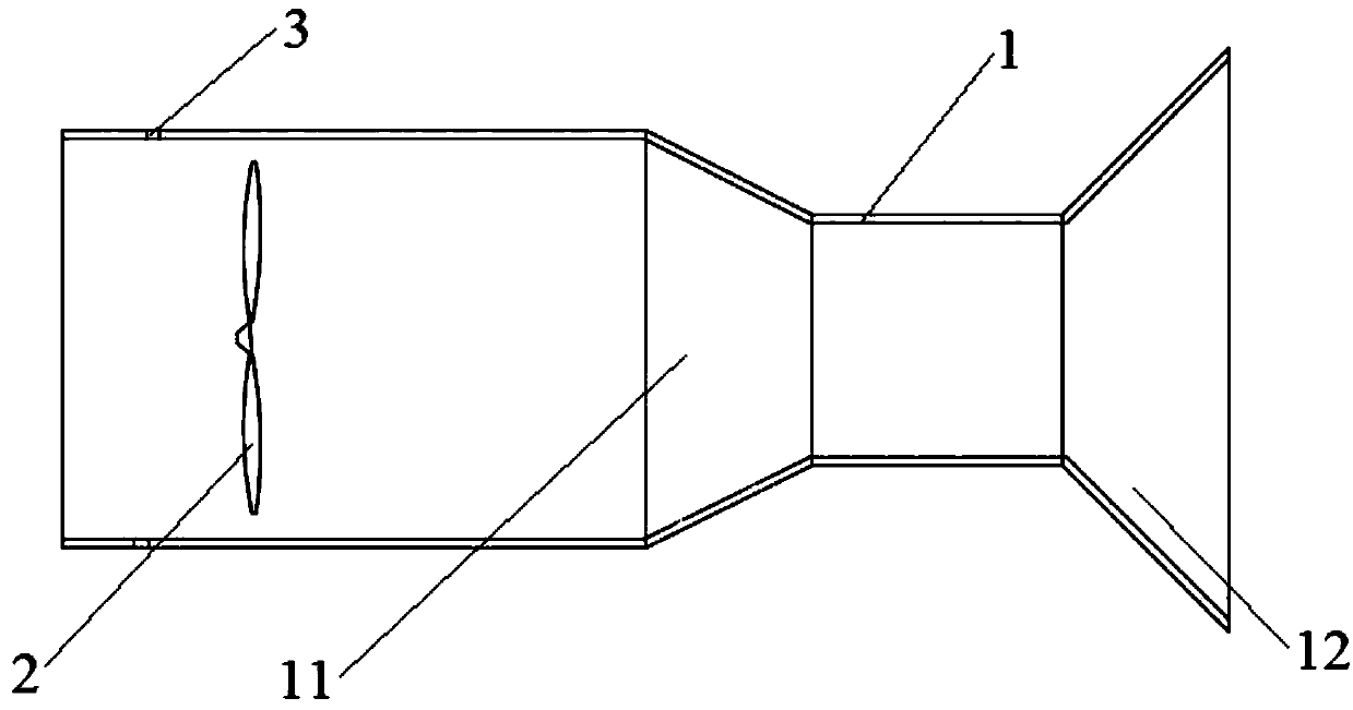
Figure 1
Abstract
Description
technical field
[0001] The invention relates to the field of marine propellers, in particular to a novel speed-increasing marine propeller. Background technique
[0002] A marine propeller is a propeller composed of a hub and a number of blades radially fixed on the hub. The propeller is installed below the waterline at the stern of the ship, and is powered by the main engine to rotate, push the water to the back of the ship, and use the reaction force of the water to push the ship forward. Ordinary transport ships have 1 to 2 propellers. For ships with high propulsion power, the number of propellers can be increased; large fast passenger ships have two to four propellers. The propeller generally has 3 to 4 blades, and the diameter depends on the horsepower and draft of the ship. The lower end does not touch the bottom of the water, and the upper end does not exceed the full-load waterline. The speed of the propeller should not be too high. The speed of the ocean cargo sh...
Examples
Embodiment Construction
[0015] refer to figure 1 A new type of speed-increasing marine propeller shown includes a propeller body 2, and a Laval nozzle 1 is provided outside the propeller body 2.
[0016] The Laval nozzle 1 includes a contraction tube 11 and an expansion tube 12, the propeller body 2 is located in the contraction tube 11 of the Laval nozzle 1, and the Laval nozzle 1 is fixed on the hull or the propeller shaft.
[0017] The shrink tube 11 wall of the Laval nozzle 1 is provided with some water inlet holes 3 or water inlet grooves 3, and the water inlet holes 3 or water inlet grooves 3 are directly fixed on the hull when the shrink pipe 11 port of the Laval nozzle 1 , as the main water intake; when the Laval nozzle 1 is fixed on the propeller shaft, it is used as a supplement to the water intake.
[0018] The working principle of the present invention is as follows: the water flow enters from the end of the contraction tube 11 and is discharged from the end of the expansion tube 12. Th...