
Valve pressure tester for pipeline
A valve pressure and testing device technology, which is used in measuring devices, fluid tightness testing, and machine/structural component testing. The effect of recovering damage and deformation, strong flexibility, improving the quality of use and testing efficiency
Patent Information
- Authority / Receiving Office
- CN · China
- Patent Type
- Applications(China)
- Current Assignee / Owner
- Publication Date
- 2018-06-08
- Estimated Expiration
- Not applicable · inactive patent
Smart Images
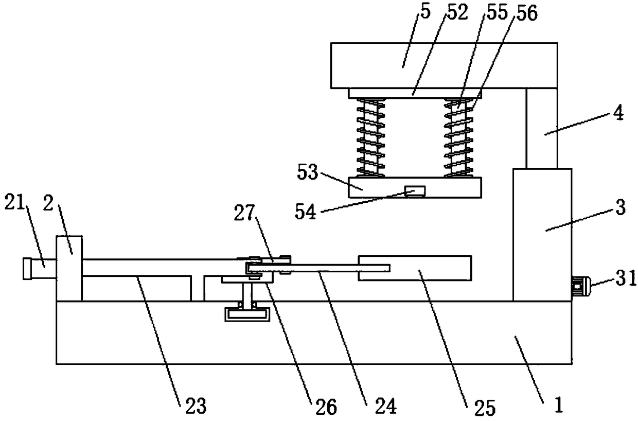
Figure 1 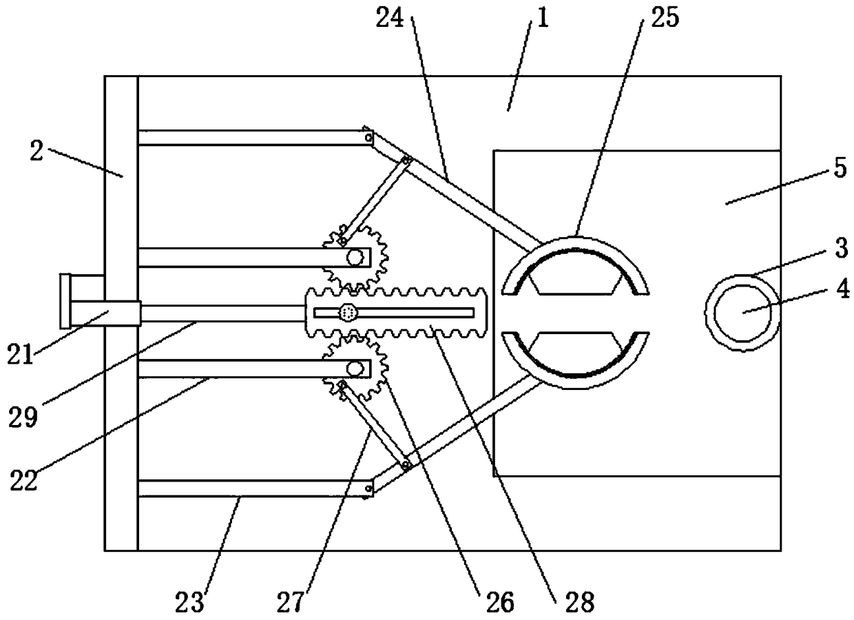
Figure 2 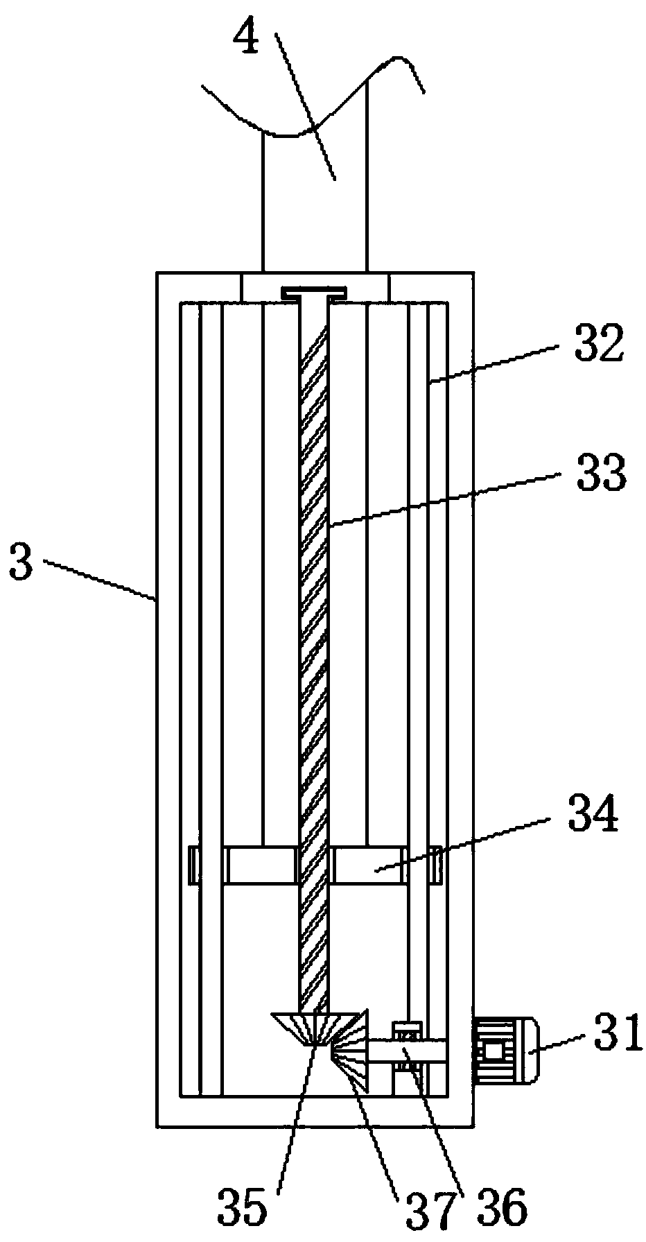
Figure 3
Abstract
Description
technical field
[0001] The invention relates to the technical field of valves, in particular to a valve pressure testing device for pipelines. Background technique
[0002] In the process of valve production, testing and maintenance, the pressure test that the valve can withstand is an important process. The valve pressure test device is an indispensable equipment for all kinds of factories that produce valves. Before the valve leaves the factory or is used by the user It needs to be tested for pressure.
[0003] The pressure test of the valve is generally completed by the manufacturer. Before the valve leaves the factory, use the valve pressure equipment to carry out the pressure test on the valve to confirm that the valve has no internal leakage, and the valve body has no defects such as micropores and cracks, and check that the pressure resistance of the valve meets the design requirements. However, valves will still leak internally after being used for a period of time,...
Examples
Embodiment
[0027] refer to Figure 1-4 , a valve pressure testing device for pipelines, including a fixed base 1, and also includes a valve fastening mechanism, a stable lifting mechanism, and a test protection mechanism that moves up and down with the stable lifting mechanism;
[0028] The valve fastening mechanism includes a positioning vertical plate 2 welded on the top side of the fixed base 1. The outer end surface of the positioning vertical plate 2 is equipped with a push rod motor 21, and the inner end surface of the positioning vertical plate 2 is respectively connected with two sets of support bars 22 and Fixed cross bar 23, two groups of supporting cross bars 22 are located between two groups of fixed cross bars 23, one end of fixed cross bar 23 is rotatably installed with adjusting long rod 24, and one end of adjusting long rod 24 is welded with valve clamping plate 25, supports One end of the cross bar 22 is rotatably equipped with a first gear 26, and the top edge of the fi...