
Horizontal landing type multi-rotor unmanned aerial vehicle body box
A multi-rotor unmanned aerial vehicle, fuselage technology, applied in the fuselage, fuselage frame, unmanned aircraft and other directions, can solve the problems of scattered installation of airborne equipment, increase the weight of the structure, increase the weight of the cable, etc. Effectiveness of internal space utilization, simplified installation process, and shortened overall length
Patent Information
- Authority / Receiving Office
- CN · China
- Patent Type
- Applications(China)
- Current Assignee / Owner
- Publication Date
- 2018-09-07
Smart Images
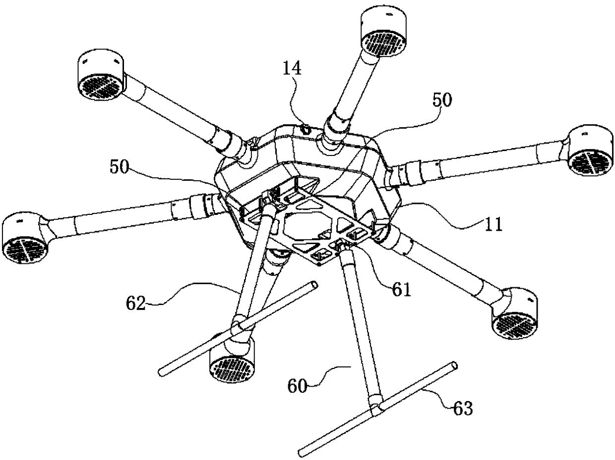
Figure 1 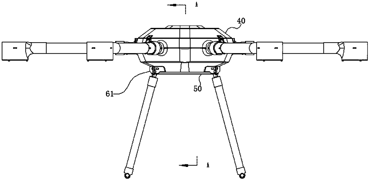
Figure 2 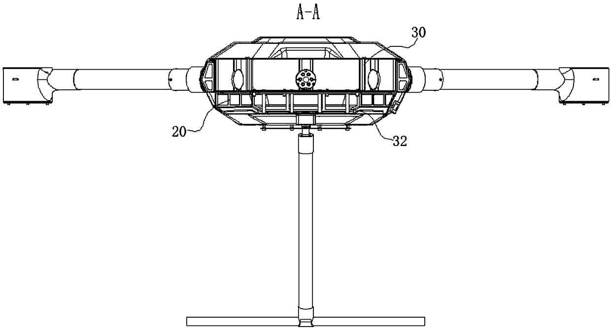
Figure 3
Abstract
Description
Technical field:
[0001] The invention relates to the technical field of multi-rotor drones, in particular to a horizontal landing type multi-rotor drone fuselage box. Background technique:
[0002] A multi-rotor UAV is a rotorcraft with more than two rotor axes. Rotated by electric motors at the end of each shaft, the rotors are driven to generate lift. The angle of the rotor is fixed rather than variable like in a helicopter. By changing the relative speed between different rotors, the propulsion torque can be changed, thereby controlling the trajectory of the aircraft. Because multi-rotors are relatively simple and stable, the current implementation of multi-rotor aircraft is much smaller than that of aircraft, so it is suitable for amateur use. Because multicopters are easy to manufacture and control, they are often used to make models and remote-controlled aircraft. The common ones are four-axis, six-axis, and eight-axis aircraft. It is small in size and light in we...
Examples
Embodiment 1
[0052] like Figure 1~3 and Figure 7 As shown, a fuselage box of a horizontal landing type multi-rotor UAV includes a polygonal fuselage shell 10, a fuselage bearing box 20 and a battery frame 30 are sequentially arranged in the fuselage shell 10, and the upper end of the fuselage shell 10 is also An upper cover 40 is provided, so that the design of the fuselage box of the UAV simplifies the main load-bearing components into a skin, a fuselage load-bearing box 20, and a battery frame 30, and the three parts are nested and glued sequentially. The traditional internal frame structure of the fuselage greatly simplifies the installation process and reduces the production cost.
[0053] like Figure 4 As shown, the fuselage shell 10 has a hexagonal structure, and the fuselage shell 10 includes a fuselage frame 11 and a skin, the skin covers the outer surface of the fuselage frame 11, and the lower end of the fuselage frame 11 protrudes inward to form a bearing bar 12. There are...
Embodiment 2
[0059] like Figure 9 , 10 11, the content of this embodiment is basically the same as that of Embodiment 1, and the similarities will not be repeated. The difference is that a horizontal landing system is also provided at the lower end of the landing gear, and the horizontal landing system includes an adaptive adjustment unit 70. Intervals are arranged at the lower end of the landing gear, and sliding terminals 71 can be slid up and down in the adaptive adjustment unit 70; the distance sensor module 80 for detecting the distance between the landing gear and the ground is arranged on the multi-rotor UAV; the drive unit 90, Arranged on the side of the adaptive adjustment unit 70, the drive unit 90 controls pressing and restricting / moving away from and releasing the sliding terminal 71 via the control module 91;
[0060] The control module 91, the drive unit 90 and the distance sensor module 80 are electrically connected; the distance sensor module 80 detects that the distance ...
Embodiment 3
[0065] like Figure 10 As shown, the content of this embodiment is basically the same as that of Embodiment 2, and the similarities will not be repeated. The difference is that the drive unit 90 includes an electric push rod arranged on one side of the limit plate 76, and the electric push rod The output end vertical limit plate 76 is arranged, and the control module 91 is electrically connected with the servo motor on the electric push rod. In this way, it is more convenient to control the electric push rod, and the electric push rod itself is a standard part, which is easier to purchase and replace. convenient.