
Test system and method of signal machine driving system
A driving system and testing system technology, applied in the direction of measuring electricity, measuring devices, measuring electrical variables, etc., can solve the problems of extremely high tester ability requirements, lack of norms and standards, and insufficient testing, so as to improve the efficiency of regression testing, Facilitate system analysis and improve the effect of automated testing
Patent Information
- Authority / Receiving Office
- CN · China
- Patent Type
- Applications(China)
- Current Assignee / Owner
- Publication Date
- 2018-10-23
Smart Images
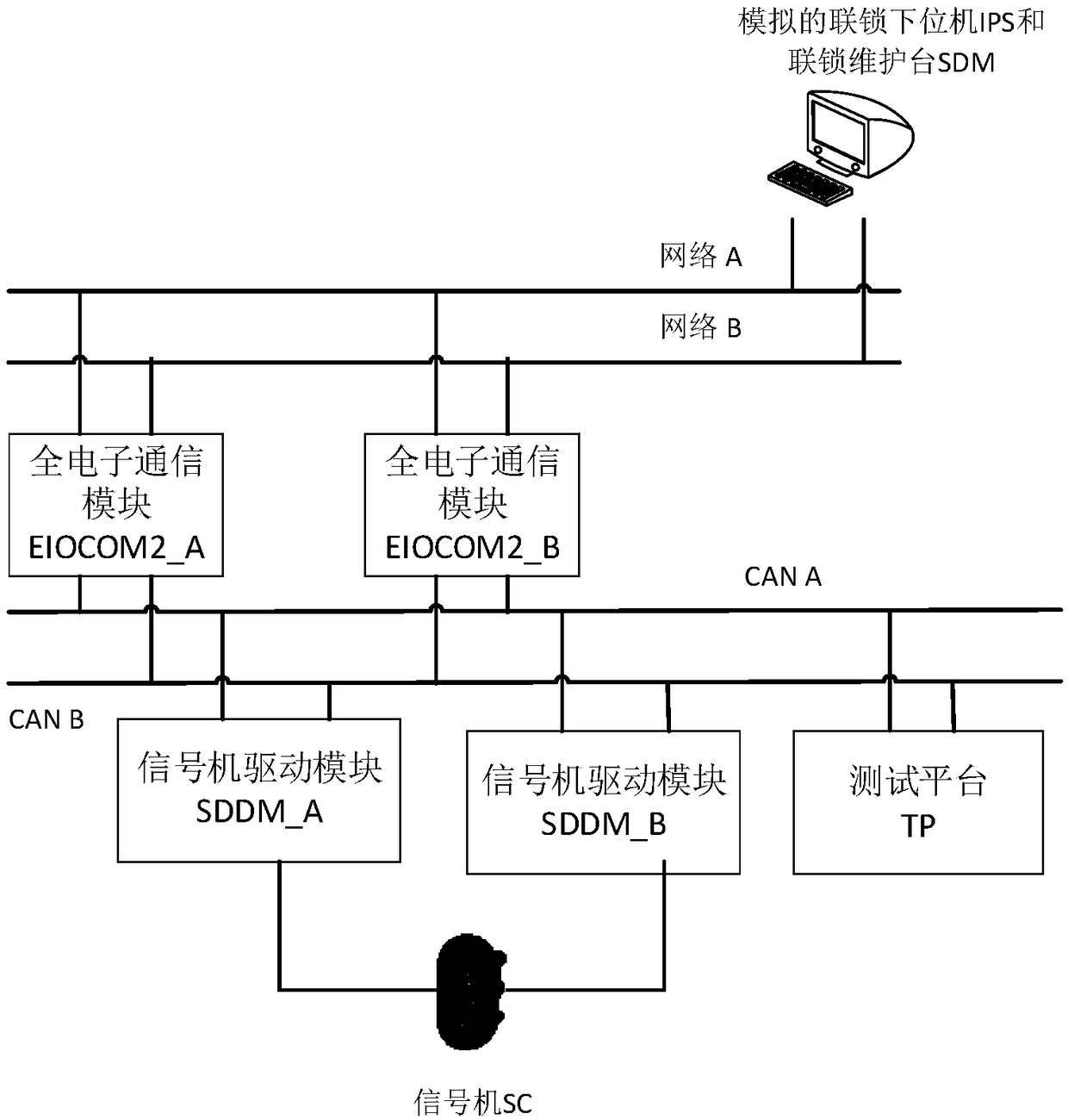
Figure 1 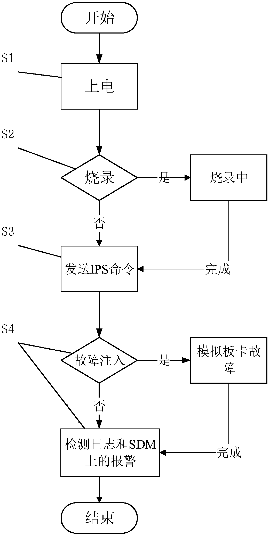
Figure 2 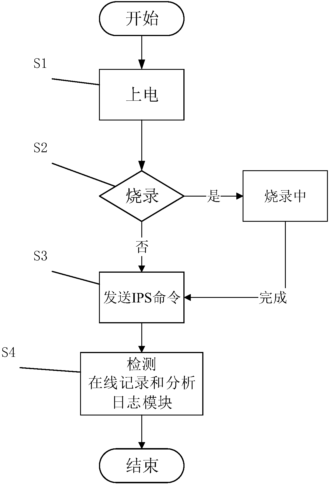
Figure 3
Abstract
Description
technical field
[0001] The invention relates to the technical field of railway traffic testing, in particular to a testing system and method for a signal machine driving system. Background technique
[0002] With the rapid development of my country's rail transit industry, more and more stations use high-performance circuit boards to replace the complex and numerous relays in the past to realize the driving and collection of signal lights, that is, to use this two-by-two-out-of-two structure signal machine The drive system is used to realize the drive and collection functions of single or combined signal lamps. The construction of this new driving system is simple, but the safety must be guaranteed. Once a defect occurs, it will cause immeasurable property losses and casualties.
[0003] Therefore, a test method for a signal drive system based on a two-by-two architecture is particularly important. At present, the test of this drive system is mainly manual testing, which ha...
Examples
Embodiment 1
[0047] Such as figure 1 As shown, a test system for a signal drive system, the signal drive system includes a signal machine SC, a signal drive module SDDM, and an all-electronic communication module EIOCOM2 connected in sequence. The test system includes a simulated interlocking lower computer IPS, The simulated interlocking maintenance platform SDM and the test platform TP; the simulated interlocking lower computer IPS and the simulated interlocking maintenance platform SDM are connected to the full electronic communication module EIOCOM2, and the test platform TP is connected to the signal machine drive module SDDM and the full electronic communication Module EIOCOM2 connection.
[0048] In this embodiment, it is a test system of a signal drive system based on a two-by-two architecture, so there are two signal drive modules SDDM: a signal drive module SDDM_A and a signal drive module SDDM_B; an all-electronic communication module EIOCOM2 Both have two: the full electronic ...
Embodiment 2
[0069] In this embodiment, the test system of the signal drive system based on the two-by-two architecture is used to verify a specific process of the multi-way switch BIT in the signal drive module SDDM, including the following steps:
[0070] Step 1. In the power-on and power-off module, power on the signal driver module SDDM;
[0071] Step 2. In the fault injection module, respectively simulate the sixth switch CPUA switching failure, CPUB switching failure, CPUA and CPUB simultaneous switching failure;
[0072] Step 3. In the online programming module, open the content of the multi-way switch fault injection according to the test script, and perform online programming of the signal driver module SDDM;
[0073] Step 4. After the programming is completed, power off the signal driver module SDDM by powering on and powering off the module, and then power on again;
[0074] Step 5, through the online recording and analysis of the log module, verify whether the BIT is successfu...