
Waste oil discharging device for cutting fluid
A discharge device and cutting fluid technology, which is applied in the direction of grease/oily substance/floating matter removal device, liquid separation, chemical instruments and methods, etc., can solve the problems of workpiece precision not meeting the design requirements, mechanical abrasion, and weakened lubrication, etc. , to achieve the effect of high waste oil removal efficiency, stable work and increased stability
Patent Information
- Authority / Receiving Office
- CN · China
- Current Assignee / Owner
- Publication Date
- 2018-11-23
Smart Images
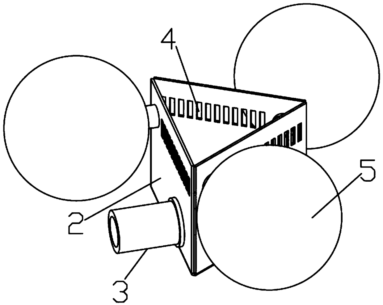
Figure 1 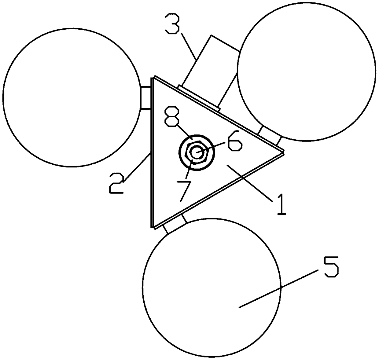
Figure 2
Abstract
Description
technical field
[0001] The invention relates to the technical field of cutting fluid purification. Background technique
[0002] During the processing of the workpiece by the machine tool, wear and high temperature will be generated due to high-speed friction between the tool and the workpiece. In order to reduce friction and reduce the high temperature generated by friction, when processing the workpiece, it is necessary to continuously spray the contact parts of the tool and the workpiece Cutting fluid, cutting fluid is recycled through the cutting fluid circulation system. Due to leakage and other reasons, it is inevitable that some machine tool lubricating oil and hydraulic oil will be mixed into the cutting fluid circulation system. As the cutting fluid circulation time continues to increase, The content of waste oil (machine lubricating oil and hydraulic oil) in the cutting fluid will increase, which will reduce the use function of the cutting fluid, weaken the lubrica...
Examples
Embodiment 1
[0023] Depend on Figure 1-2 It can be seen from the illustrated embodiment that this embodiment includes a waste oil collection tank and a structure for generating uniform buoyancy in the collection tank; the waste oil collection tank includes a tank body, a waste oil discharge port 3, a waste oil collection structure and a counterweight installation structure, and the tank body includes The tank bottom wall 1 and the tank peripheral wall 2 are closed together in the circumferential direction of the tank peripheral wall 2. The bottom end of the tank peripheral wall 2 is sealed and connected with the peripheral edge of the tank bottom wall 1. The center of gravity of the tank body is located at the center point of the bottom of the waste oil collection tank. On the vertical line; the waste oil outlet 3 is arranged on the tank body, the counterweight installation structure is arranged at the center of the bottom wall 1 of the tank, and the waste oil collection structure is arran...
Embodiment 2
[0029] The difference between this embodiment and Embodiment 1 is that the counterweight installation structure includes a screw and a counterweight, the screw is vertically arranged at the center of the inner bottom of the bottom wall of the tank, and there is at least one counterweight, which is an annular body and is sleeved on the screw superior. In this way, the screw rod is vertically arranged in the inner cavity of the tank body, which is convenient for adjusting the weight of the tank body at any time during work (the lower edge of each oil inlet 4 is located at the height of the oil slick layer) without turning the device upside down to adjust, which will affect the stability of the center of gravity of the tank body have a certain influence.
[0030] According to the shape and size of the tank body, it is determined whether the counterweight is located above or below the bottom wall of the tank, so as not to affect the stability of the tank body during the waste oil ...