
A centrifugal separation drum machine
A technology of centrifugal separation and drum machine, which is applied in the direction of centrifuges and centrifuges with rotating drums, etc. It can solve the problems of accurately adjusting the amount of output, synchronous rotation, and small centrifuge processing capacity, and achieves easy replacement. Damaged parts, easy outlet flow, and high adjustment accuracy
Patent Information
- Authority / Receiving Office
- CN · China
- Patent Type
- Patents(China)
- Current Assignee / Owner
- Publication Date
- 2020-05-15
Smart Images
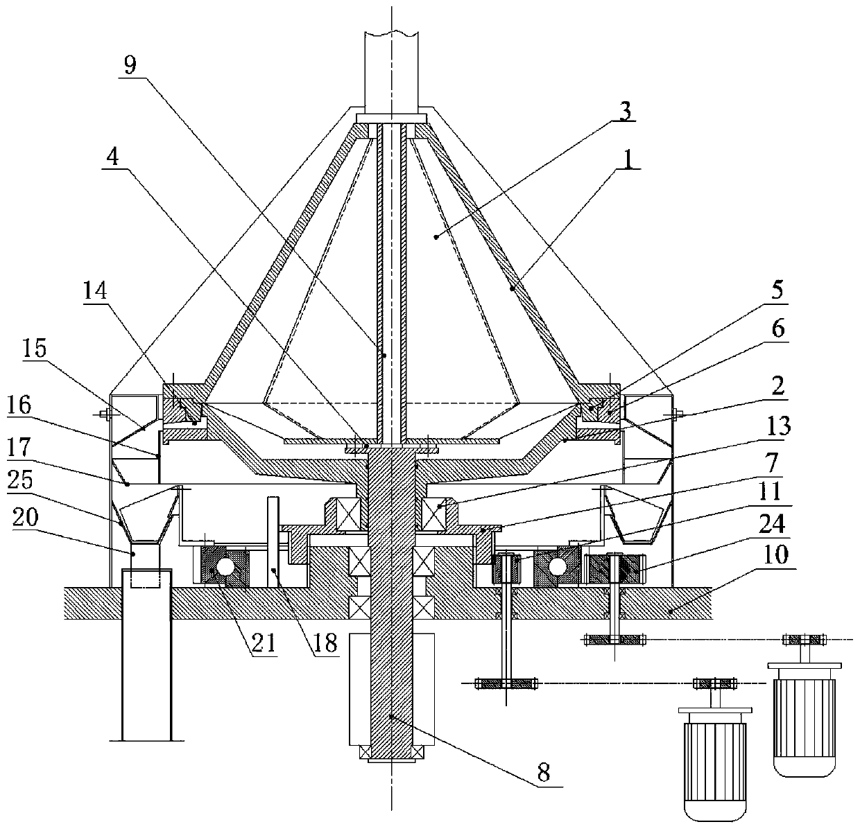
Figure 1 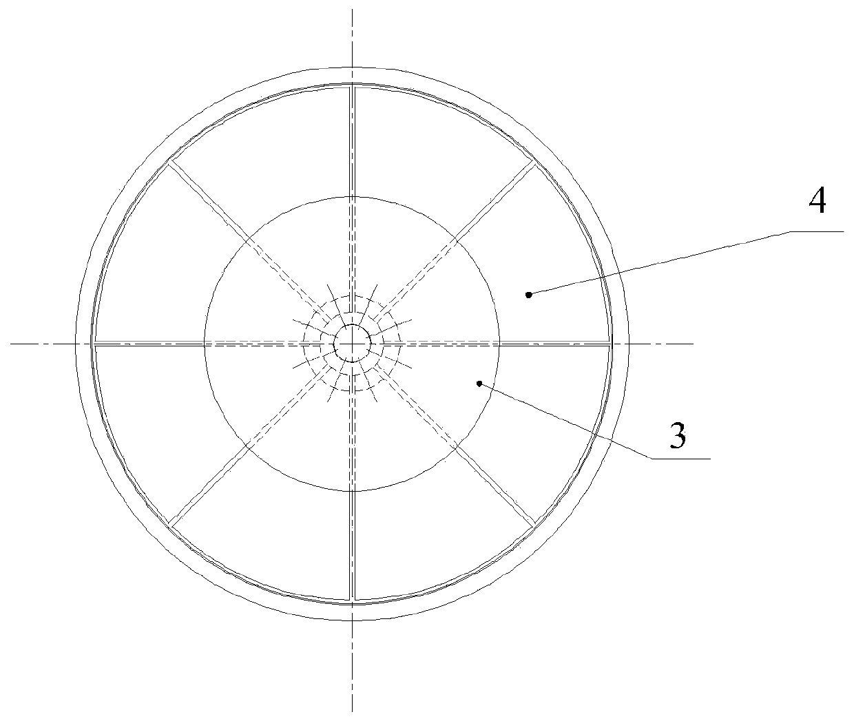
Figure 2 
Figure 3
Abstract
Description
technical field
[0001] The invention relates to the field of drum machine equipment for both centrifugal demulsification and solid-liquid separation, in particular to a drum machine for centrifugal separation. Background technique
[0002] As we all know, the vertical gravity discharge centrifuge is widely used in pharmaceutical, chemical, food and other industries. Its main function is to separate and dry the liquid components in the material. There is a bearing seat, a main shaft is arranged in the bearing seat, a drum body is set on the main shaft, a discharge port is provided at the lower part of the drum body, and a discharge hopper is provided below the discharge port; the drum body is provided with a cylindrical Drum, the cylindrical drum is provided with filter holes, the inner wall is provided with a filter screen, the base is provided with a ring-shaped liquid baffle, the outer side of the drum body is provided with an organic casing, and the gap between the liquid...
Examples
Embodiment Construction
[0034] The present invention will be further described below in conjunction with the accompanying drawings and specific embodiments, but the protection scope of the present invention is not limited thereto.
[0035] Such as figure 1 and figure 2 As shown, the centrifugal separation drum machine of the present invention includes an upper drum 1, a lower drum 2, a slag discharge retaining ring 5, a positioning ring 6, a drive shaft 8 and a rotating slag scraping system; the upper drum 1 The interior is divided into several separation chambers 3 in the radial direction, and the separation chamber 3 is provided with a liquid outlet at the top of the upper drum 1, and the upper drum 1 is provided with a feed pipe 9 inside, and the feed pipe 9 Located at the axial position of the upper drum 1, one end of the feed pipe 9 is connected to the top of the upper drum 1, and the other end of the feed pipe 9 is installed with the feed distribution plate 4, and the feed pipe 9 passes throu...