
Hole flanging die structure and stamping method
A technology of turning holes and molds, which is applied in the directions of forming tools, manufacturing tools, metal processing equipment, etc., can solve the problems of large deformation, poor flatness of the straight wall of the flanging hole of the round tube, poor appearance quality, etc. The effect of good flatness, good appearance and high quality
Patent Information
- Authority / Receiving Office
- CN · China
- Patent Type
- Applications(China)
- Current Assignee / Owner
- Publication Date
- 2019-02-01
Smart Images
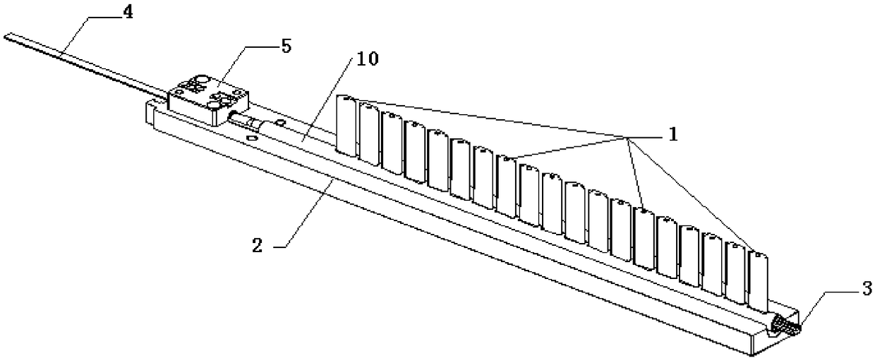
Figure 1 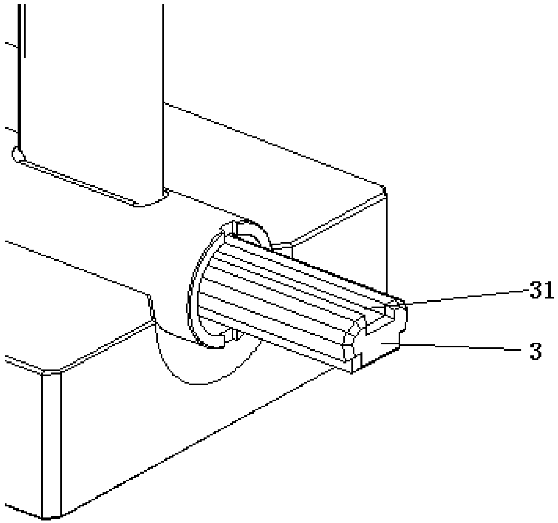
Figure 2 
Figure 3
Abstract
Description
technical field
[0001] The invention relates to the technical field of collecting pipe processing, in particular to a punching die structure and a stamping method. Background technique
[0002] The header in the air conditioner is one of the four important components of the refrigeration system. Fluorine is compressed by the compressor to produce high-temperature and high-pressure gas, which turns into a low-temperature and high-pressure liquid after cooling and condensing through the condenser, and enters the header for collecting And shunt, because it has high heat exchange efficiency and extremely low energy loss, it is widely used.
[0003] Its shape is a thin-walled straight-through round tube made of hard aluminum alloy. On the highest point of the cross section, a number of long flanging holes are evenly distributed along the length direction. The flat tube must be firmly fixed in the hole to closely match it and ensure good sealing. The conventional stamping structu...
Examples
Embodiment 1
[0061] Such as figure 1 -7 shows a specific embodiment of a hole turning mold structure, including a lower template 2 , a first mandrel 3 and a second mandrel 4 . The first end of the first mandrel 3 is fixed on the fixed block 5, the second end of the first mandrel 3 is suspended, and the lower template 2 is equipped with a fixed block matching the shape of the fixed block 5. Cavity, the fixed block 5 is installed in the fixed block installation cavity and fixed by inserting a pin, the lower template 2 is provided with a support groove 8, and the length direction of the support groove 8 is parallel to the length direction of the first mandrel 3 Setting, in this embodiment, the surface of the support groove 8 is an arc-shaped groove that matches the shape of the lower surface of the round tube 10, and the round tube 10 is sleeved behind the first mandrel 3 to connect with the support The bottom of the groove 8 is in contact. The first mandrel 3 is provided with a groove 31 c...
Embodiment 2
[0071] This embodiment provides a punching method, using the punching die structure provided in Embodiment 1 to punch and punch a tubular structure, including the following steps:
[0072] In the installation step of the tubular structure, the tubular structure is sleeved on the outside of the fixed first mandrel 3 and supported by the lower formwork 2; the second mandrel 4 is inserted into the tubular structure so that the second expansion of the second mandrel 4 The surface cooperates with the first expansion surface of the first mandrel 3, so that the side walls on both sides of the groove 31 of the first mandrel 3 closely fit the inner wall of the tubular structure;
[0073] In the stamping step, the punch 1 of the stamping structure moves downward, the punch 1 passes through the tubular structure and forms a flanging hole on the tubular structure and is supported by the groove 31 of the first mandrel 3, and the punch 1 of the stamping structure moves upward Exit the tubul...