
Water-gas separation technology for production and injection in same well through electric submersible pump
A technology of submersible electric pump and same well production and injection, which is applied in the direction of production fluid, earthwork drilling and production, wellbore/well components, etc., which can solve the problems of gas well production damage, environmental pollution, non-compliance, etc., and increase the gas production of gas wells , the effect of good technology
Patent Information
- Authority / Receiving Office
- CN · China
- Patent Type
- Applications(China)
- Current Assignee / Owner
- Publication Date
- 2019-02-01
Smart Images
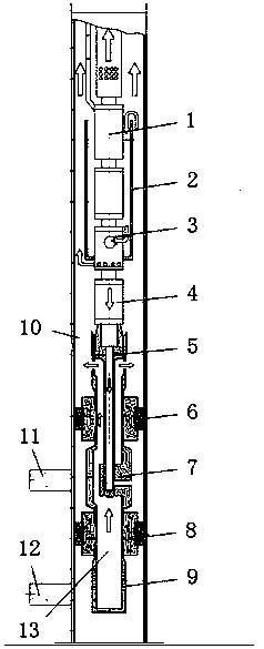
Figure 1
Abstract
Description
technical field
[0001] The invention relates to the technical field of separation of water and gas in the same well production and injection, in particular to a technology for separating water and gas in the same well production and injection using a submersible electric pump. Background technique
[0002] During the production process of gas wells, it is easy to produce gas and water simultaneously. The water production of gas wells will cause liquid accumulation in gas wells, which will seriously damage the production of gas wells, and eventually cause gas wells to stop production due to water flooding. Currently, drainage gas production is commonly used The lifting system is to discharge the separated liquid to the ground, but the water (well fluid) cannot be effectively used, or even discharged randomly, which pollutes the environment and does not meet the current requirements of building a resource-saving and environment-friendly society. . Moreover, the current liftin...
Examples
Embodiment Construction
[0023] The following will clearly and completely describe the technical solutions in the embodiments of the present invention with reference to the accompanying drawings in the embodiments of the present invention. Obviously, the described embodiments are only some, not all, embodiments of the present invention.
[0024] refer to figure 1 , a water-gas separation technology using electric submersible pumps in the same well production and injection, including electric submersible pump unit 1, gas-liquid separation guide device 2, gas-liquid diversion device 7, gas-liquid channel 10 and packer layered sealing system 13 , the packer layered sealing system 13 is composed of a first packer 6, a second packer 8 and a screen 9, and the first packer 6 is located above the second packer 8, and the gas-liquid splitting device 7 is located between the first packer 6 and the second divider 8, the bottom of the sealing cannula 5 is inserted into the inner cavity of the gas-liquid separatio...