

A damping pilot valve sleeve control on-off valve
A pilot valve sleeve and pilot valve technology, applied in servo motor components, mechanical equipment, fluid pressure actuators, etc., can solve problems such as the inability to overcome the hydraulic force to push the valve core, increase the volume of the switch valve, and reduce the reliability of the valve. , to achieve the effect of improving the ability to resist external disturbances, reducing the specification size, weight and installation size
Patent Information
- Authority / Receiving Office
- CN · China
- Patent Type
- Patents(China)
- Current Assignee / Owner
- Publication Date
- 2020-09-22
Smart Images
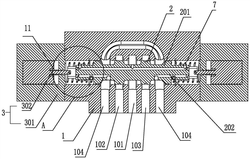
Figure 1 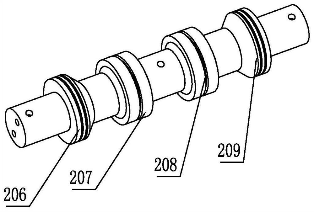
Figure 2 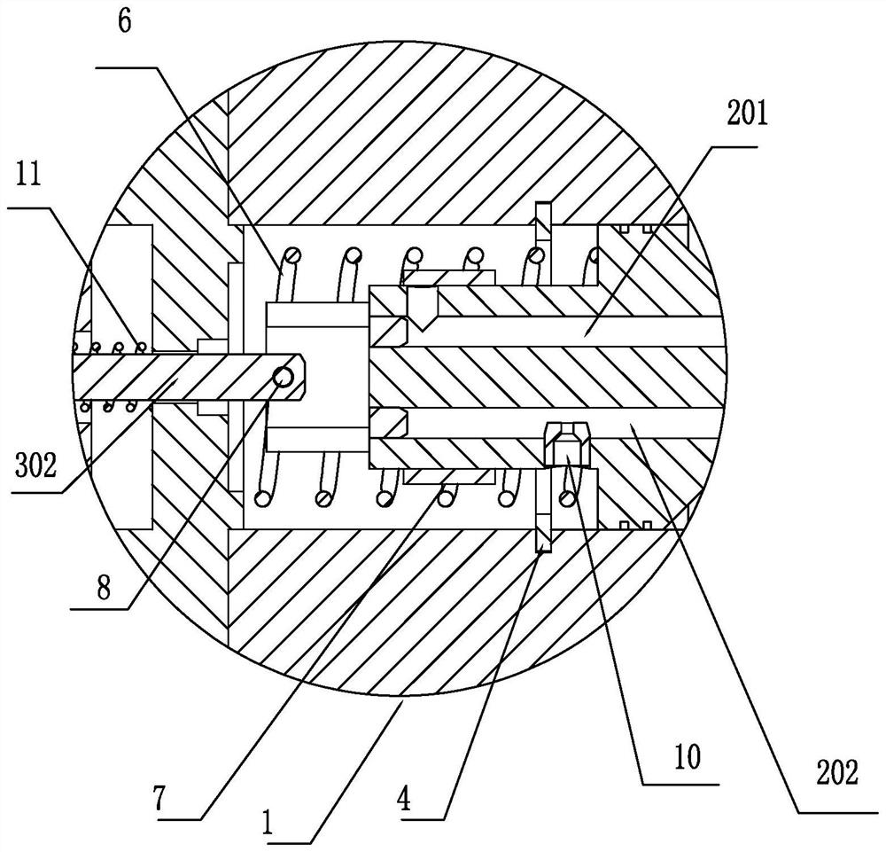
Figure 3
Abstract
Description
technical field
[0001] The invention belongs to the field of fluid transmission and control, and in particular relates to a damping pilot valve sleeve control on-off valve. Background technique
[0002] Fluid control valves, especially hydraulic valves, play the role of controlling flow, pressure and switching oil circuits. For example, the electromagnetic switch valve plays the role of controlling the flow and switching the oil circuit; the electromagnetic switch valve is divided into a single-stage valve direct-acting valve and a two-stage valve pilot control valve according to the flow capacity. In the industry standard, the single-stage valve direct-acting valve is divided into 6 passages and 10 passages; the two-stage valve pilot control valve is divided into 16, 25, 32... The larger the passage number, the larger the valve volume, The flow capacity is also greater.
[0003] The fluid switch control valve used for small flow is generally in the form of a single-stage ...
Examples
Embodiment 1
[0032] Such as figure 1 As shown, a damping pilot sleeve control on-off valve includes a valve body 1 and a main valve core 2. The valve body 1 is provided with a high-pressure oil inlet 101, a first control oil port 102, and a second control oil port. 103. The two low-pressure oil outlets 104 can be at zero pressure, the two low-pressure oil outlets 104 are set on both sides, the high-pressure oil inlet 101 is set in the middle, and the first control oil port 102 and the second control oil port 103 are respectively set Between the two low-pressure oil outlets 104 and the high-pressure oil inlet 101, such as figure 2As shown, the main valve core 2 is provided with a first protruding ring 206, a second protruding ring 207, a third protruding ring 208, and a fourth protruding ring 209 in the circumferential direction, and the first protruding ring 206 and the fourth protruding ring 209 are located at two The end and the dynamic sealing cooperation with the valve body 1 can imp...
Embodiment 2
[0043] The difference from Embodiment 1 is that when the electromagnet 301 is energized, the electromagnetic armature 302 is rotated, and the pilot valve sleeve 7 includes a cylindrical main body 701 adapted to the outer periphery of the main valve core. The cylindrical main body 701 is provided with a through hole 703, and the rotation of the electromagnetic armature 302 drives the pilot valve sleeve 7 to rotate axially relative to the main valve core 2 so that the through hole 703 communicates with or staggers the oil inlet passage 201 so that Block the oil inlet passage 201.
[0044] When the electromagnet is not energized, the oil inlet channel 201 is closed, so the hydraulic pressure at both ends of the main valve core is low pressure. The second position where the oil port 103 and the low-pressure oil outlet 104 are separated from each other;
[0045] When the left electromagnet is energized, the left pilot valve sleeve 7 rotates so that the left oil inlet passage 201 i...
Embodiment 3
[0049] Such as Figure 7 As shown, an on-off valve controlled by an inflow damping pilot valve sleeve includes a valve body 1 and a main valve core 2. The valve body 1 is provided with a high-pressure oil inlet 101, a first control oil port 102, and a second control oil port. The port 103 and the two low-pressure oil outlets 104 can be at zero pressure, the two low-pressure oil outlets 104 are arranged on both sides, the high-pressure oil inlet 101 is arranged in the middle, and the first control oil port 102 and the second control oil port 103 are respectively Set between the two low-pressure oil outlets 104 and the high-pressure oil inlet 101, such as figure 2 As shown, the main valve core 2 is provided with a first protruding ring 206, a second protruding ring 207, a third protruding ring 208, and a fourth protruding ring 209 in the circumferential direction, and the first protruding ring 206 and the fourth protruding ring 209 are located at two The end and the dynamic se...