
Shaft connection structure
A technology for connecting structures and connecting shafts, which is applied in the direction of shaft couplings, rigid shaft couplings, mechanical equipment, etc., can solve the problems of power transmission shafts that cannot transmit power, and achieve good power transmission quality, good connection contact, and connection contact. large area effect
Patent Information
- Authority / Receiving Office
- CN · China
- Current Assignee / Owner
- Publication Date
- 2019-04-09
Smart Images
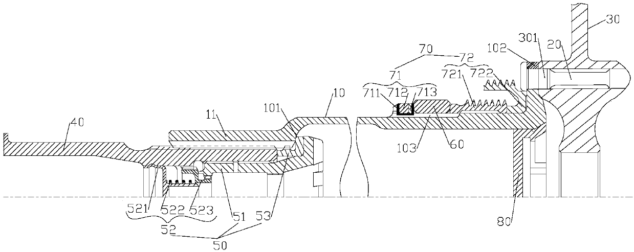
Figure 1 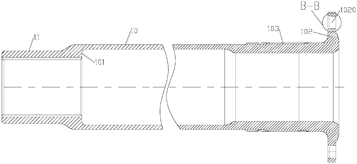
Figure 2 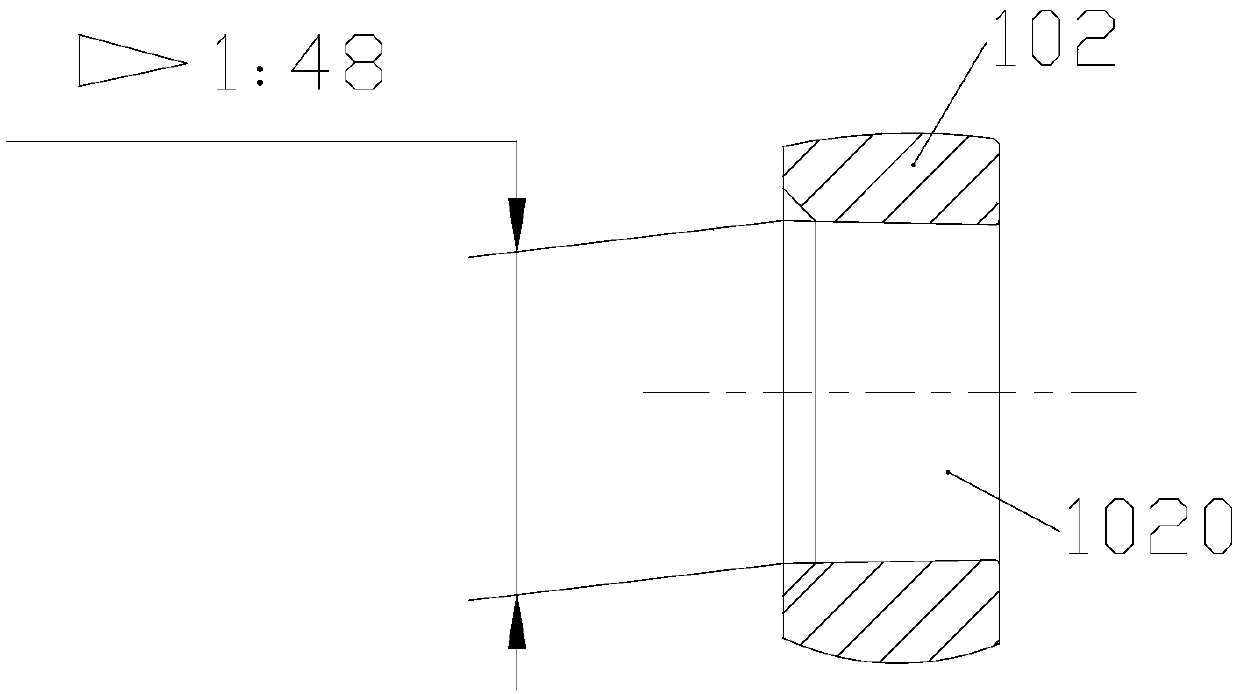
Figure 3
Abstract
Description
technical field
[0001] The invention relates to the field of aero-engines, in particular to a shaft connection structure. Background technique
[0002] The power transmission shaft is one of the important structural parts of the turboprop aero-engine. The input end of the shaft is connected with the turbine disk in the turbine part, and the output end of the shaft is connected with the rear journal of the compressor, which is used to rotate the turbine rotor in the turbine part. The generated power is transferred to the compressor, accessory drive and propeller via the power transfer shaft. In the prior art, the input end of the power transmission shaft is connected to the turbine disk through tension bolts, and the output end of the power transmission shaft is connected to the rear journal of the compressor through an internal and external spline structure. Since the power transmission shaft works in the environment of high temperature, high pressure and high-speed air flo...
Examples
Embodiment Construction
[0023] The embodiments of the present invention will be described in detail below with reference to the accompanying drawings, but the present invention can be implemented in many different ways defined and covered by the claims.
[0024] refer to figure 1 , the preferred embodiment of the present invention provides a shaft connection structure, which is connected between the turbine part and the compressor part, and is used to transmit the power of the turbine part to the compressor part. The shaft connection structure includes: a hollow shaft connected at both ends The connection shaft 10, the input end of the connection shaft 10 is detachably fixedly connected with the turbine disk 30 of the turbine component through the fixed connection piece 20, so as to prevent relative movement between the connection shaft 10 and the turbine disk 30. The shaft hole at the output end of the connecting shaft 10 is provided with a limit step 101 protruding toward its center, and the output...