
A structure of a highly sealed liquid flow control ball valve which is convenient for connection
A high-sealing, liquid technology, used in valve devices, cocks including cut-off devices, mechanical equipment, etc., can solve problems such as poor flow regulation effect of ball valves, and achieve the effect of enhanced sealing effect and reduced airbag.
Patent Information
- Authority / Receiving Office
- CN · China
- Patent Type
- Patents(China)
- Current Assignee / Owner
- Publication Date
- 2020-08-25
Smart Images
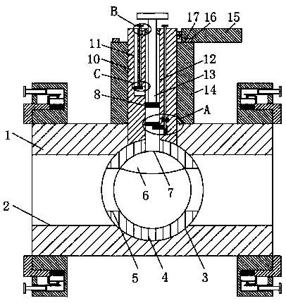
Figure 1 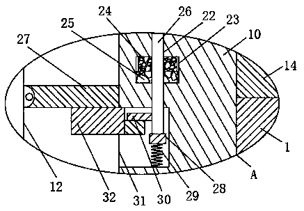
Figure 2 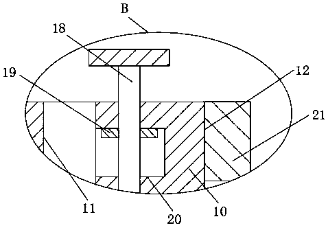
Figure 3
Abstract
Description
Technical field
[0001] The present invention relates to the technical field of ball valves, in particular to a structure of a high-sealing liquid flow control ball valve that is convenient for connection. Background technique
[0002] A ball valve is an opening and closing part, a valve that is driven by the valve stem and rotates around the axis of the ball valve; it can also be used for fluid adjustment and control. Among them, the hard-sealed V-shaped ball valve has a V-shaped ball core and a metal valve made of surfacing hard alloy. There is a strong shear force between the seats, which is especially suitable for media containing fibers, small solid particles, etc.; and the multi-way ball valve in the pipeline can not only flexibly control the confluence, divergence, and flow direction switching of the media, but also Close any channel to connect the other two channels; this type of valve should generally be installed horizontally in the pipeline; ball valves are divided into...
Examples
Embodiment
[0023] Reference Figure 1-4 , An easy-to-connect structure of a high-sealing liquid flow control ball valve, including a housing 1, a water channel 2 is provided on the side wall of the housing 1, a rotating groove 3 is provided on the inner wall of the water channel 2, and the inner wall of the rotating groove 3 is slidingly connected with a hollow The inner wall of the symmetrical two ends of the sphere 4 is provided with a circulation hole 5, the upper inner wall of the sphere 4 is glued with an airbag 6, and the upper end side wall of the sphere 4 is penetrated with a vent groove 7, which communicates with the interior of the airbag 6. The upper end of the sphere 4 is welded with a rotating shaft 10, and the upper end of the shell 1 is welded with a rotating shell 14. The rotating shaft 10 penetrates the upper wall of the shell 1 and the rotatable shell 14 and extends to the upper end of the rotating shell 14. The inside of the rotating shaft 10 is provided with a limited f...