
Full-automatic tapping machine capable of recycling scraps
A fully automatic, tapping machine technology, applied in the direction of thread cutting machine, maintenance and safety accessories, metal processing machinery parts, etc., can solve the problems of affecting work efficiency, difficult waste disposal, cumbersome operation, etc., to reduce work intensity and structure Simplicity and efficiency-enhancing effects
Patent Information
- Authority / Receiving Office
- CN · China
- Patent Type
- Applications(China)
- Current Assignee / Owner
- Publication Date
- 2019-06-11
- Estimated Expiration
- Not applicable · inactive patent
Smart Images
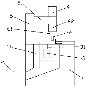
Figure 1 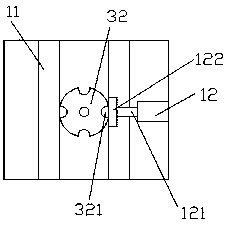
Figure 2
Abstract
Description
technical field
[0001] The invention relates to the technical field of mechanical equipment, in particular to a fully automatic tapping machine with waste recycling. Background technique
[0002] At present, there is a fully automatic tapping machine with waste chip recycling. During the tapping process of parts, the waste chips are difficult to deal with, and the staff need to manually process and recycle them, which greatly increases the labor intensity of the staff. Secondly, it cannot To realize fully automatic tapping, the structure is complex, the operation is cumbersome and other deficiencies, thus affecting the work efficiency. Contents of the invention
[0003] The object of the present invention is to provide a fully automatic tapping machine with waste chip recovery, which solves the problems raised in the background technology.
[0004] In order to achieve the above object, the present invention provides the following technical solutions: a full-automatic tapp...
Examples
Embodiment approach
[0015] As a preferred embodiment of the present invention, the first motor 3 is arranged in the middle of the base 1 and is fixedly connected with the base 1, the working disc 32 is arranged in the middle of the upper end of the base 1, and Through the rotating shaft 31 and the first motor 3, the working semi-circular hole 321 is opened on the outer side of the front of the working disc 32; The middle of the upper right side of the seat 1 is fixedly connected with the machine base 1, the pressure head 122 is arranged on the right side of the working semicircular hole 321, and is movably connected by the telescopic rod 121 and the telescopic arm 12; the support column 5 It is arranged in the middle of the left side of the upper end of the machine base 1, and is fixedly connected with the machine base 1, and the second motor 4 is arranged at the upper side of the working disk 32, and is fixedly connected by the support rod 51 and the support column 5; The tapping head 6 is arran...