
A rotary robot welding jig and its working method
A robotic welding and rotary technology, applied in welding equipment, auxiliary welding equipment, welding/cutting auxiliary equipment, etc., can solve the problems of low space utilization, low degree of automation, time-consuming and labor-intensive, etc., and achieve accurate positioning of welding work , high degree of automation, time-saving and labor-saving effect
Patent Information
- Authority / Receiving Office
- CN · China
- Patent Type
- Patents(China)
- Current Assignee / Owner
- Publication Date
- 2021-03-19
Smart Images
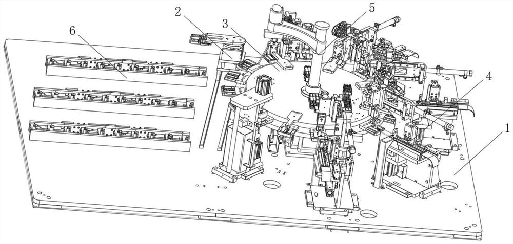
Figure 1 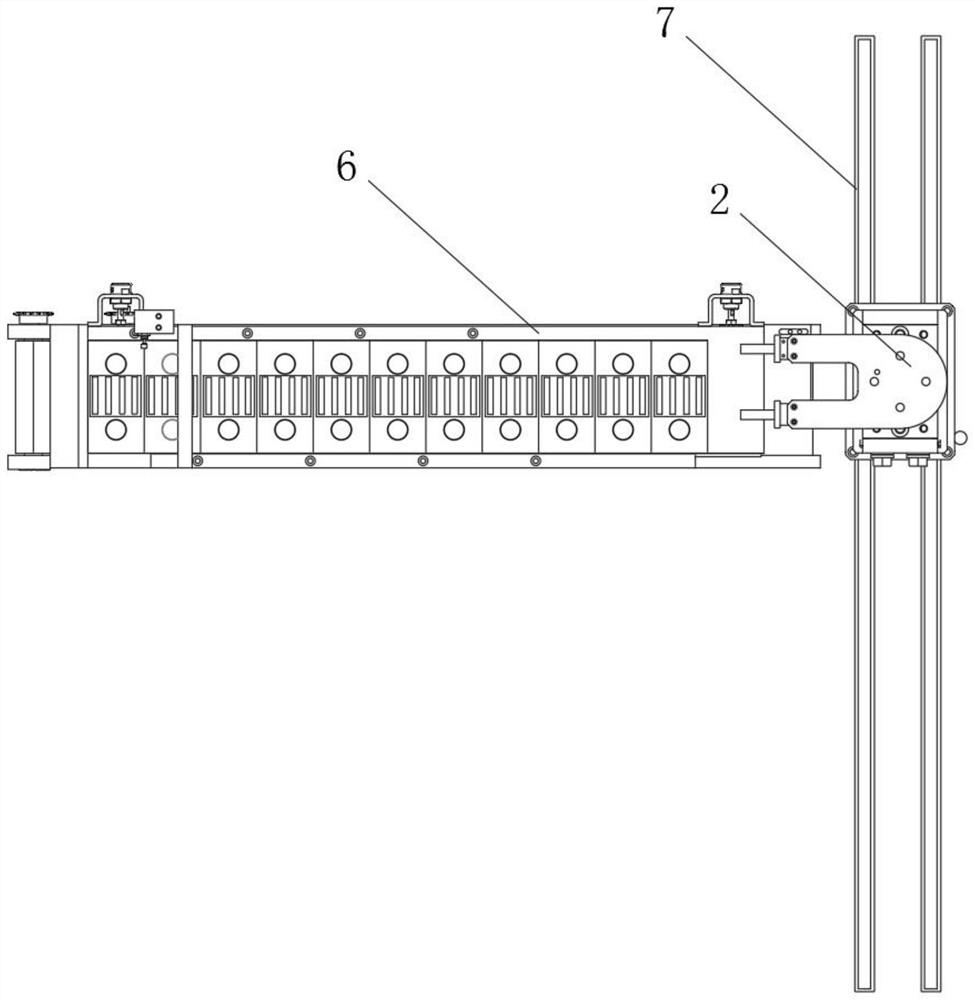
Figure 2 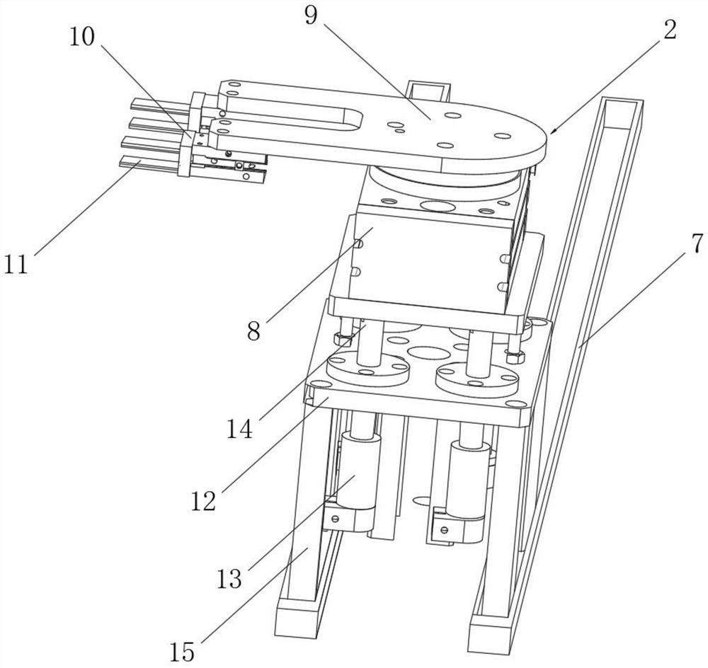
Figure 3
Abstract
Description
technical field
[0001] The invention relates to a welding jig, in particular to a rotary robot welding jig and a working method thereof, belonging to the technical field of protection device applications. Background technique
[0002] With the rapid development of people's living standards, robots are used more and more widely in daily life, such as sweeping robots used in households, intelligent processing robots used in factories, etc. There are many kinds of robots and different types.
[0003] When the robot is being processed, it is necessary to separate the various parts of the robot for welding processing. When welding the robot parts, the welding fixture is indispensable. Its main function is to clamp and fix the robot parts, so that the welding equipment can be used for robot parts. Welding process.
[0004] There are still many deficiencies in the existing robot welding fixtures when they are in use. The existing robot welding fixtures are time-consuming and labor...
Examples
Embodiment Construction
[0046] The technical solutions of the present invention will be clearly and completely described below in conjunction with the embodiments. Apparently, the described embodiments are only some of the embodiments of the present invention, not all of them. Based on the embodiments of the present invention, all other embodiments obtained by persons of ordinary skill in the art without creative efforts fall within the protection scope of the present invention.
[0047] see Figure 1-14 As shown, a rotary robot welding fixture includes a swing table 1, a front clamp seat 2, a rear chuck 3 and a side pressure seat 4, the front clamp seat 2 is arranged above the swing table 1, and the front clamp seat 2 is a A circular rear chuck 3 is arranged on the side, and several side pressure seats 4 are arranged on the edge of the rear chuck 3 in an equal arc;
[0048] A first motor 8 is arranged above the front clamp seat 2, and a rotating plate 9 is connected to the top of the first motor 8,...