
Automatic scanning, measuring and analyzing device and method for engineering tire winding tread shape
An automatic scanning, measurement and analysis technology, applied in the direction of measuring devices, optical devices, tires, etc., can solve the problems of cumbersome measurement process, reduce production efficiency, waste production time, etc., achieve simple use, improve accuracy and efficiency, and reduce detection cost effect
Patent Information
- Authority / Receiving Office
- CN · China
- Patent Type
- Applications(China)
- Current Assignee / Owner
- Publication Date
- 2019-08-30
Smart Images
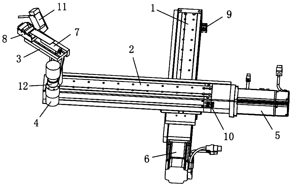
Figure 1 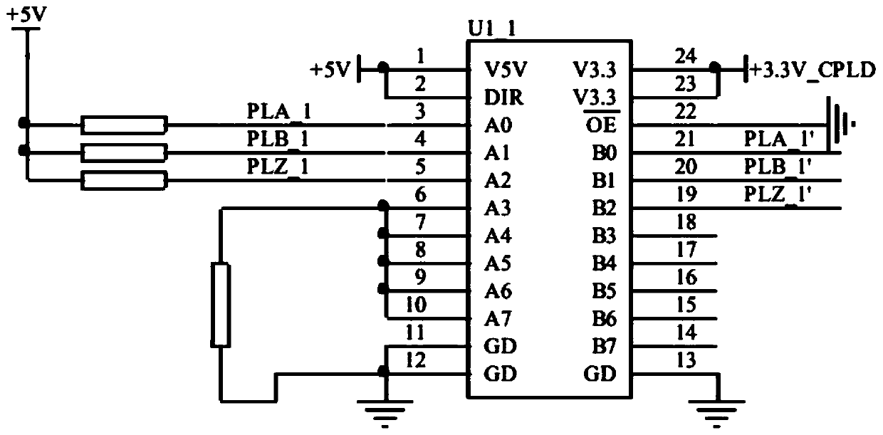
Figure 2 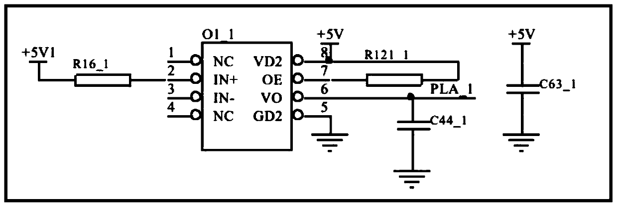
Figure 3
Abstract
Description
technical field
[0001] The invention relates to a device and a method, in particular to an automatic scanning measurement and analysis device and method for the shape of an engineering tire winding tread. Background technique
[0002] In the engineering tire winding process, the tire embryo starts to rotate under the drive of the rotary machine, and the rubber strip is wound on the tire embryo to form a tread. For a certain type of tire, the shape of the tread has specified requirements, so according to the preset program, the number of turns of winding is different at different positions to form a tread of the specified shape. Since the thickness of the rubber strip changes from time to time, it is wound according to the predetermined number of turns. Generally speaking, the shape of the tread cannot fully meet the specified requirements, but as long as it is within the error range. So how do you know whether the shape of the tread has reached the specified error range? ...
Examples
Embodiment Construction
[0041] The present invention will be described in further detail below in combination with specific embodiments.
[0042] figure 1 An engineering tire winding tread shape automatic scanning measurement analysis device includes a winding machine; the winding machine includes an X-axis moving track 1 moving along the X-axis direction, a Y-axis moving track 2 moving along the Y-axis direction, and a Y-axis moving track 2 moving along the Z-axis direction. The Z-axis moving track that moves in the axial direction 3, the No. 1 stepping motor that controls the rotation of the Z-axis moving track 4, the No. 2 stepping motor that controls the movement of the Y-axis moving track 5, and the No. 3 stepping motor that controls the movement of the X-axis moving track 6. Cylinder 7 and winding machine head 8; the Y-axis moving track is slidingly connected to the X-axis moving track, and the Y-axis moving track is connected to the Z-axis moving track through a sliding column. The winding ma...