
Fresh air system exhaust device with purification function for traffic tunnel
A technology for a fresh air system and an exhaust device, which is applied to ventilation systems, household appliances, cleaning methods and appliances, etc., can solve the problems of reduced purification capacity, reduced practicability of exhaust devices, low temperature of three-way catalytic converters, etc. The effect of purification ability, improved usability, and easy access
Patent Information
- Authority / Receiving Office
- CN · China
- Current Assignee / Owner
- Publication Date
- 2019-11-22
- Estimated Expiration
- Not applicable · inactive patent
Smart Images
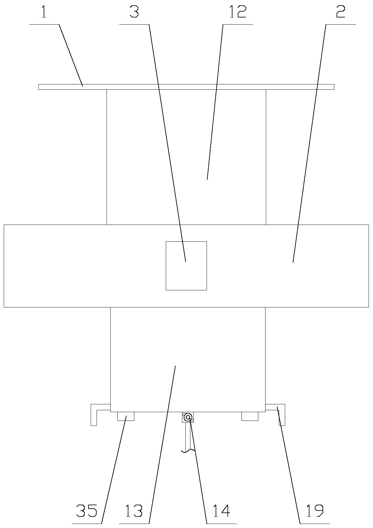
Figure 1 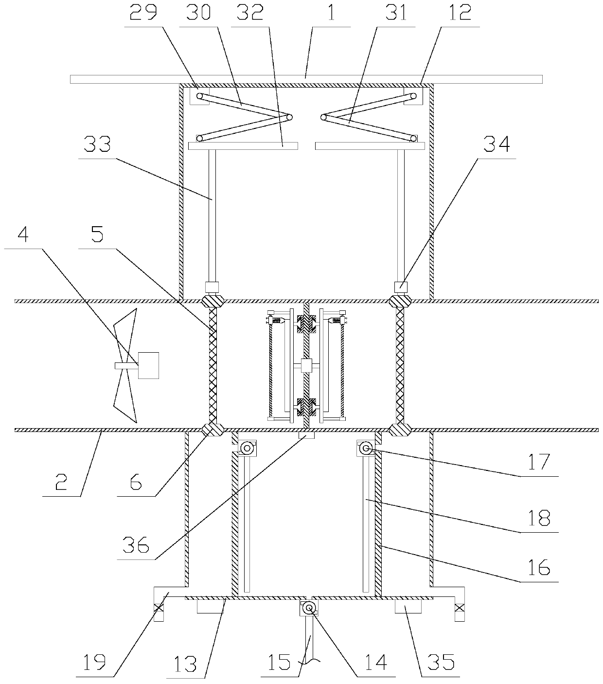
Figure 2 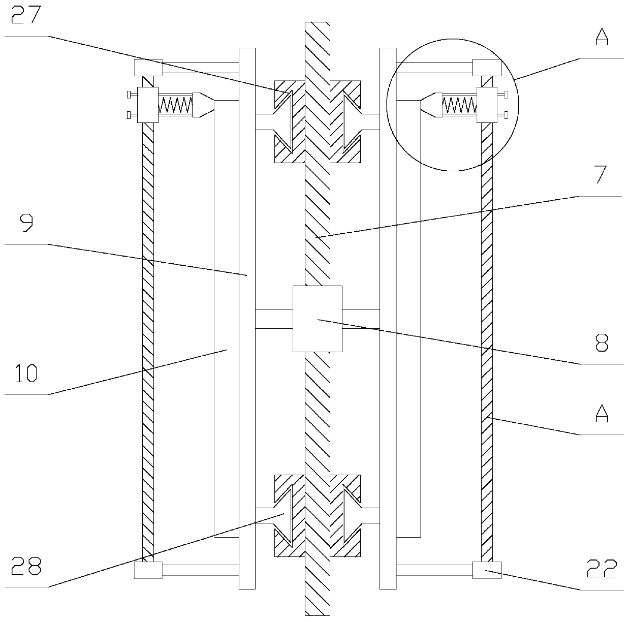
Figure 3
Abstract
Description
technical field
[0001] The invention relates to the field of fresh air systems, in particular to an exhaust device for a fresh air system with purification function used in traffic tunnels. Background technique
[0002] The fresh air system is based on sending fresh air to the room with special equipment on one side of the closed room, and then exhausting it from the other side to the outside by special equipment. A "fresh air flow field" will be formed indoors to meet the needs of indoor fresh air ventilation. The plan is: use the wind pressure, large flow fan, remove the mechanical force to send air to the room from one side, and use a specially designed exhaust fan to exhaust the room from the other side to force the formation of a fresh air flow field in the system.
[0003] However, when the existing fresh air system is used inside the underground traffic tunnel, the exhaust device directly discharges the air in the tunnel to the external atmosphere, and because a large...
Examples
Embodiment Construction
[0024] The present invention is described in further detail now in conjunction with accompanying drawing. These drawings are all simplified schematic diagrams, which only illustrate the basic structure of the present invention in a schematic manner, so they only show the configurations related to the present invention.
[0025] Such as Figure 1-2 As shown, a fresh air system exhaust device with purification function for traffic tunnels includes a roof 1, an exhaust pipe 2, a processor 3 and a cleaning mechanism. The exhaust pipe 2 is arranged under the roof 1, so The processor 3 is fixed on the exhaust pipe 2, and the processor 3 is provided with an antenna and PLC, and the exhaust pipe 2 is provided with a fan 4, a heating mechanism and two catalytic nets 5, and the fan 4 is connected to the exhaust pipe 2. The PLC is electrically connected, the heating mechanism is located between two catalytic nets 5, the outer periphery of the catalytic net 5 is provided with a frame 6, ...