
Efficient electromagnetic pulse valve and working method thereof
An electromagnetic pulse valve, high-efficiency technology, applied in the direction of the valve operation/release device, valve details, diaphragm valve, etc., can solve the problems of the dust removal effect of the dust collector, the air supply time becomes longer, the diaphragm cracks and fails, etc., to achieve enhanced reliability Performance and service life, improved circulation efficiency, and fast pulse action
Patent Information
- Authority / Receiving Office
- CN · China
- Patent Type
- Applications(China)
- Current Assignee / Owner
- Publication Date
- 2020-02-04
Smart Images
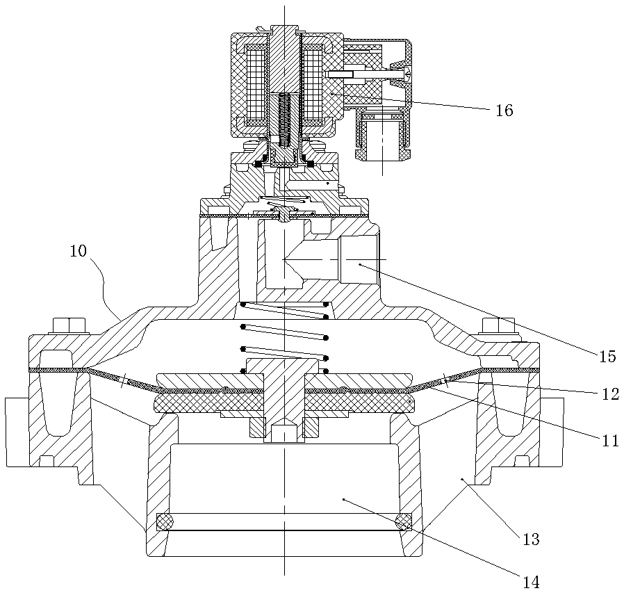
Figure 1 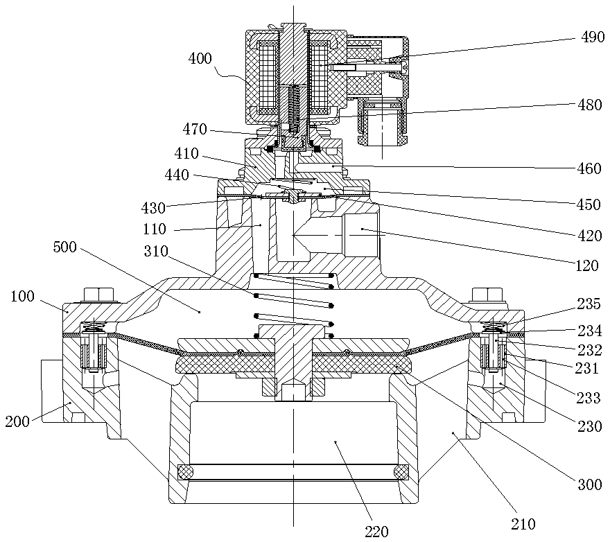
Figure 2 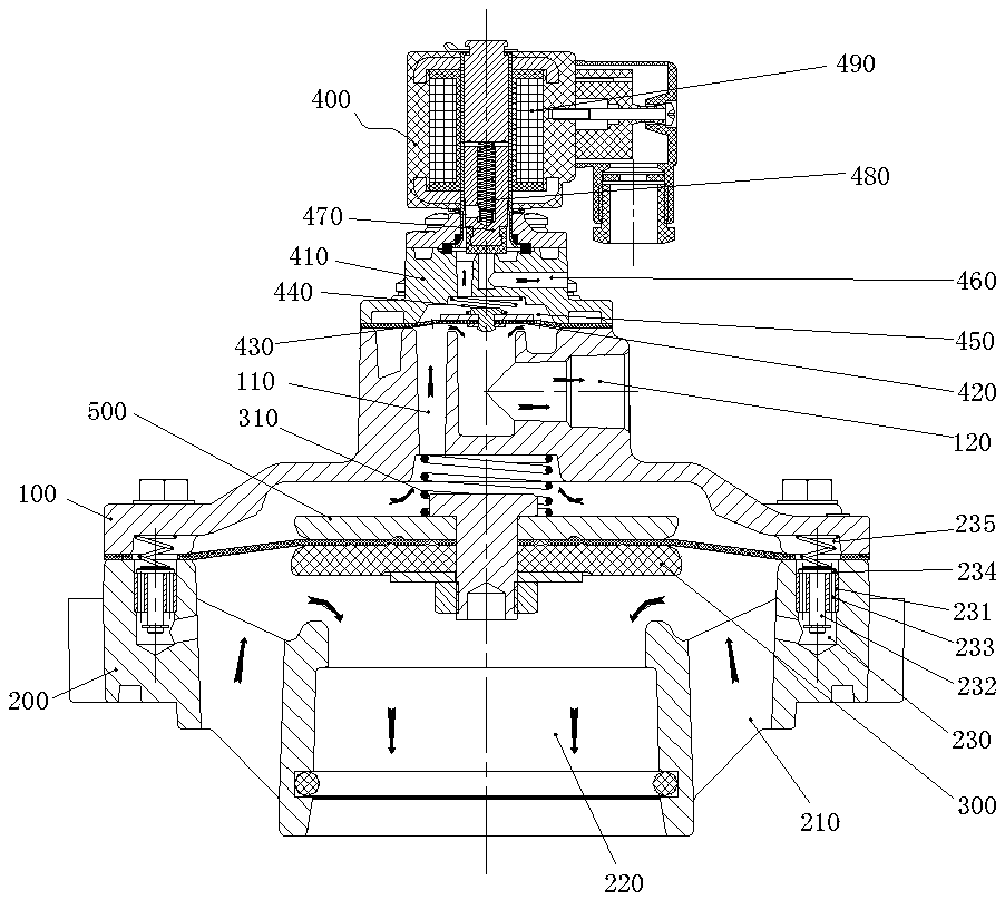
Figure 3
Abstract
Description
technical field
[0001] The invention relates to a high-efficiency electromagnetic pulse valve and its working method. Background technique
[0002] The pulse valve refers to the diaphragm valve that is controlled by the pilot valve such as electromagnetic or pneumatic, and can open and close the high-pressure air source in an instant to generate pulses. The pulse valve is the main component of the bag filter. The existing pulse valve communicates with the upper and lower air chambers of the diaphragm by setting an orifice on the diaphragm. When working, when the electromagnetic coil of the control valve is energized, the armature assembly is lifted upward under the action of electromagnetic force, and the pressure is released. The hole is opened and the gas is discharged. Due to the throttling effect of the diaphragm orifice, the gas flow out of the pressure relief hole is greater than the gas flow of the gas flowing into the rear air chamber through the orifice, so that the...
Examples
Embodiment Construction
[0019] Such as Figure 2~6 As shown, a high-efficiency electromagnetic pulse valve includes an upper valve seat 100 and a lower valve seat 200, an inlet passage 210 is arranged on the edge of the lower valve seat 200, an air outlet passage 220 is arranged at the center of the lower valve seat 200, and an air outlet passage 220 is arranged on the upper valve seat 100 and the lower valve seat 200. A first diaphragm assembly 300 is arranged between the lower valve seat 200 to block the inlet passage 210 and the outlet passage 220, a first spring 310 is arranged between the first diaphragm assembly 300 and the upper valve seat 100, and the upper valve The upper end of the seat 100 is also provided with a control valve 400 capable of attracting the first diaphragm assembly 300 to move upwards, and a first air chamber 500 is provided between the first diaphragm assembly 300 and the upper valve seat 100, which is characterized in that: the lower valve seat On 200, along the central a...