
Tension test equipment and steel wire rope tension test method thereof
A tension test and steel wire rope technology, applied in the direction of applying stable tension/pressure to test the strength of materials, measuring devices, instruments, etc., can solve problems such as unstable clamping force, loose clamps and wire ropes, and failure to meet the needs of use. Achieve the effect of accurate tensile test results, improve accuracy, and improve stability
Patent Information
- Authority / Receiving Office
- CN · China
- Patent Type
- Applications(China)
- Current Assignee / Owner
- Publication Date
- 2020-06-16
Smart Images
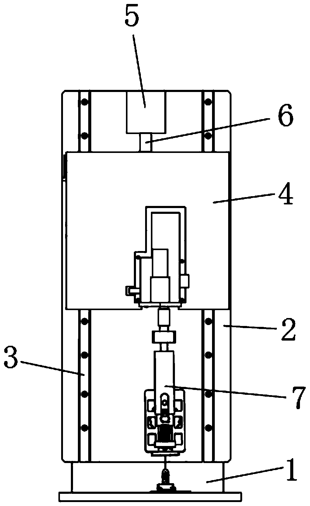
Figure 1 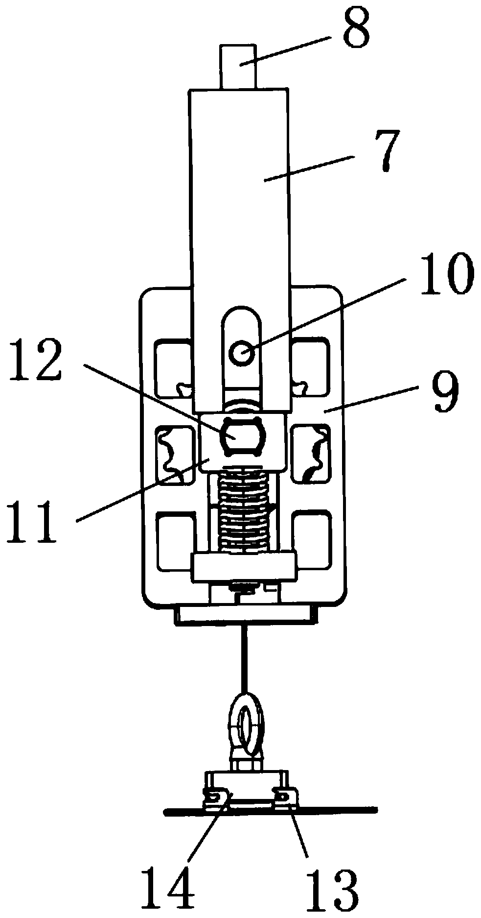
Figure 2 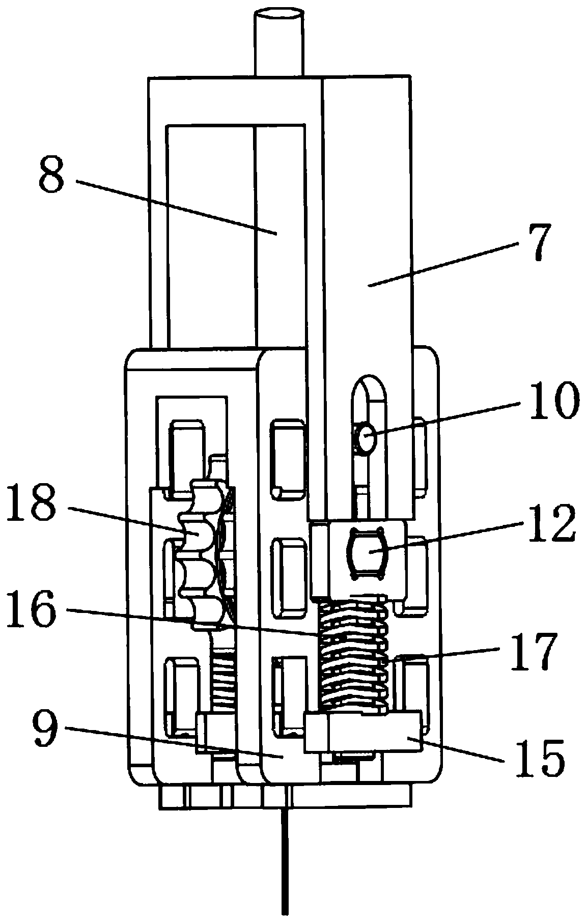
Figure 3
Abstract
Description
technical field
[0001] The invention relates to the field of test equipment, in particular to a tension test equipment and a method for performing a steel wire rope tension test, belonging to the technical field of tension test equipment applications. Background technique
[0002] The tensile test of materials is mainly to determine the tensile properties of materials, and the quality of tensile properties can be detected by tensile tests. Tensile test (stress-strain test) generally clamps the two ends of the material sample on two fixtures at a certain distance, separates the two fixtures at a certain speed and stretches the sample, and measures the stress change on the sample. until the sample fails. Tensile test is one of the most widely used methods to study the mechanical strength of materials. When the existing steel wire rope tensile test equipment is used for tensile test, the steel wire rope is mainly clamped and fixed by the clamp of the tensile test, so that the ...
Examples
Embodiment Construction
[0030] The technical solutions of the present invention will be clearly and completely described below in conjunction with the embodiments. Apparently, the described embodiments are only some of the embodiments of the present invention, not all of them. Based on the embodiments of the present invention, all other embodiments obtained by persons of ordinary skill in the art without creative efforts fall within the protection scope of the present invention.
[0031] see Figure 1-6, a tensile test device, comprising: a card wheel 18 for clamping and fixing a steel wire rope, a connecting shaft 12 for fixing and supporting the card wheel 18, and a drive motor 5 for driving the first bracket 7 to move to drive the steel wire rope to stretch, The card wheel 18 is symmetrically arranged on one end of the connecting shaft 12, and the card wheel 18 is rotatably connected with the connecting shaft 12 through a key. 9 Fixed connection, the cross section of the connecting shaft 12 is a ...