
Part cleanliness detection device and detection method
A detection device and component technology, applied in measurement devices, particle size analysis, material weighing, etc., can solve the problems of filter membrane pore blockage, cumbersome steps, reduced detection speed and detection accuracy, etc., to improve detection speed and simplify detection. process, the effect of improving inspection speed and efficiency
Patent Information
- Authority / Receiving Office
- CN · China
- Current Assignee / Owner
- Publication Date
- 2020-08-07
Smart Images
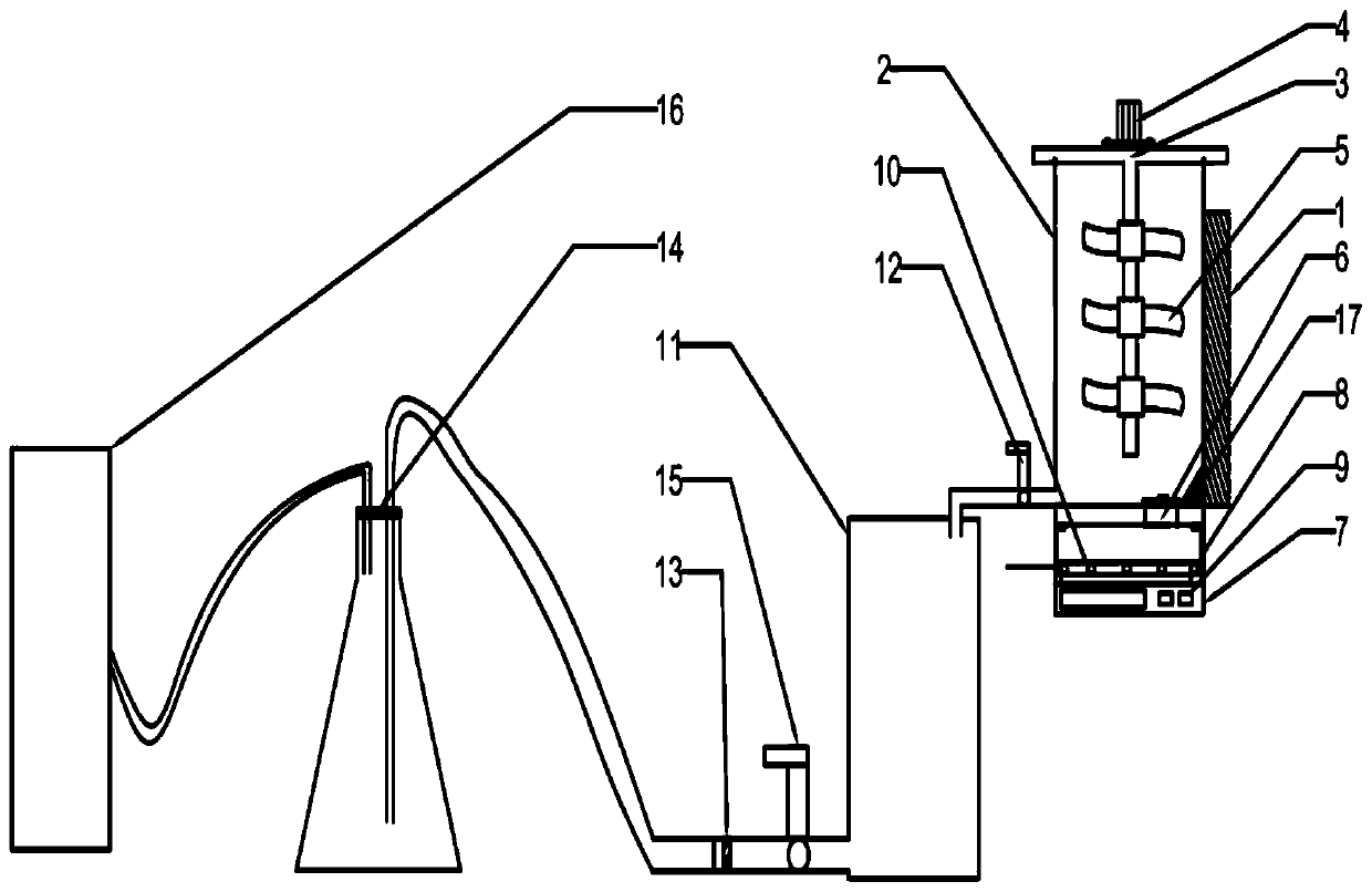
Figure 1 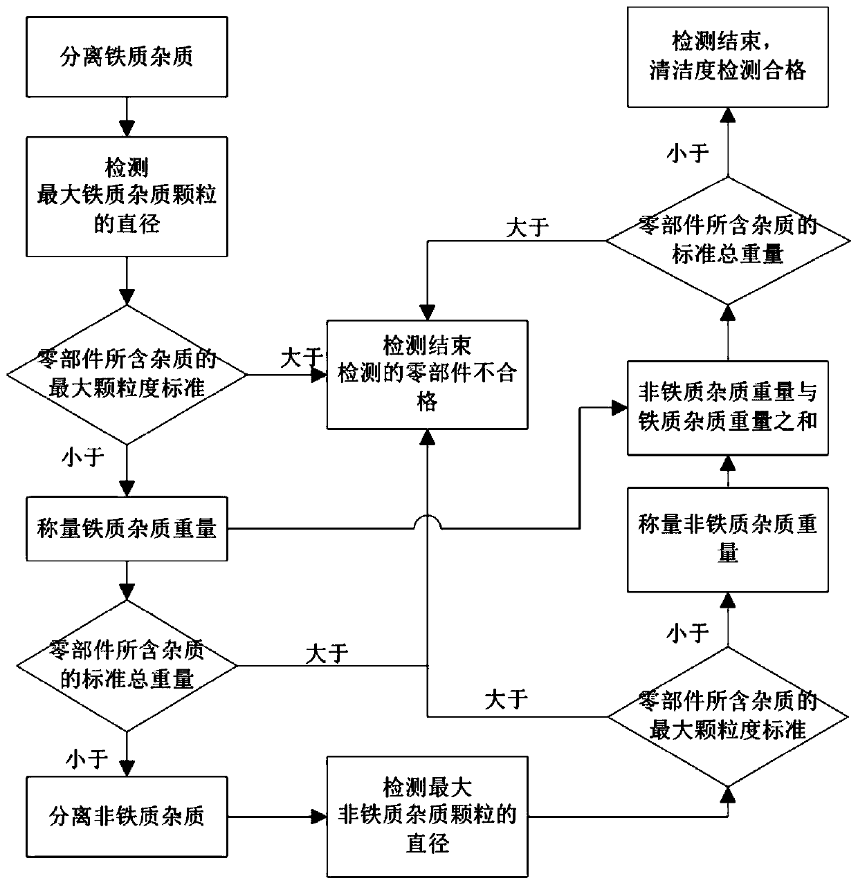
Figure 2
Abstract
Description
technical field
[0001] The invention relates to the technical field of component quality detection, in particular to a component cleanliness detection device and detection method. Background technique
[0002] In the factory inspection of automobile engines and transmission components, the inspection of cleanliness is the most basic inspection item and an important indicator to measure the quality of parts. Impurities adhering to parts may cause equipment failure, failure, and loss of control, and the tolerance of key transmission parts also has high requirements. If there are more pollutants between moving parts, it will accelerate the wear of parts and cause the whole machine to be damaged. Life shortened or scrapped. The purpose of component cleanliness testing is to eliminate or minimize early product failures to keep the cleanliness of components within the range of their pollution tolerance, so as to ensure the reliability and service life of components.
[0003] At ...
Examples
Embodiment Construction
[0028] The present invention will be further described below in conjunction with the embodiments and accompanying drawings. The specific embodiments are only used to further describe the present invention in detail, and do not limit the protection scope of the present application.
[0029] Such as figure 1 As shown, the invention provides a component cleanliness detection device (abbreviation detection device, see figure 1 ), including electromagnet 1, test solution storage container 2, drive motor 4, paddle 5, tray 8, electronic balance 9, test solution buffer bottle 11, filter membrane 13, recovery bottle 14 and vacuum pump 16;
[0030] The test solution storage container 2 is made of an iron material that can be adsorbed by an electromagnet. The top opening is provided with a top cover 3, and the bottom has a liquid outlet hole and is sealed by a bottom plug 6; the test solution storage container 2 is placed on On the supporting seat 7, the top of the supporting seat 7 is ...