
Accurate axial centering device for wire harness
A centering device and axial technology, applied in the manufacture of wire harnesses, conductor/cable insulation, electrical components, etc., can solve the problems of surface glue overflow, hidden quality, waste of manpower, etc., to ensure stability and reliability, The effect of product quality improvement and convenient pick-and-place process
Patent Information
- Authority / Receiving Office
- CN · China
- Patent Type
- Applications(China)
- Current Assignee / Owner
- Publication Date
- 2020-09-22
Smart Images
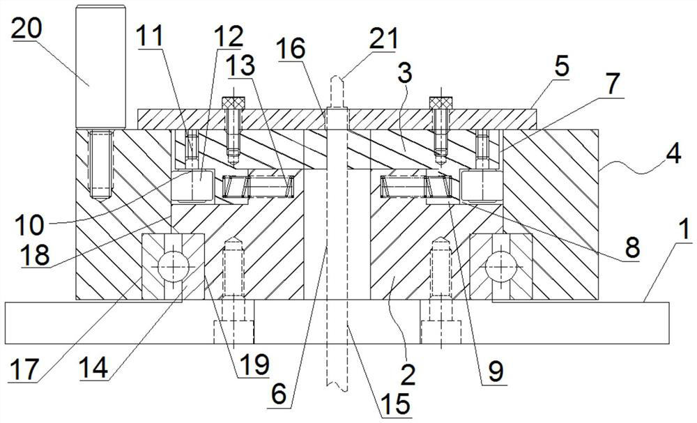
Figure 1 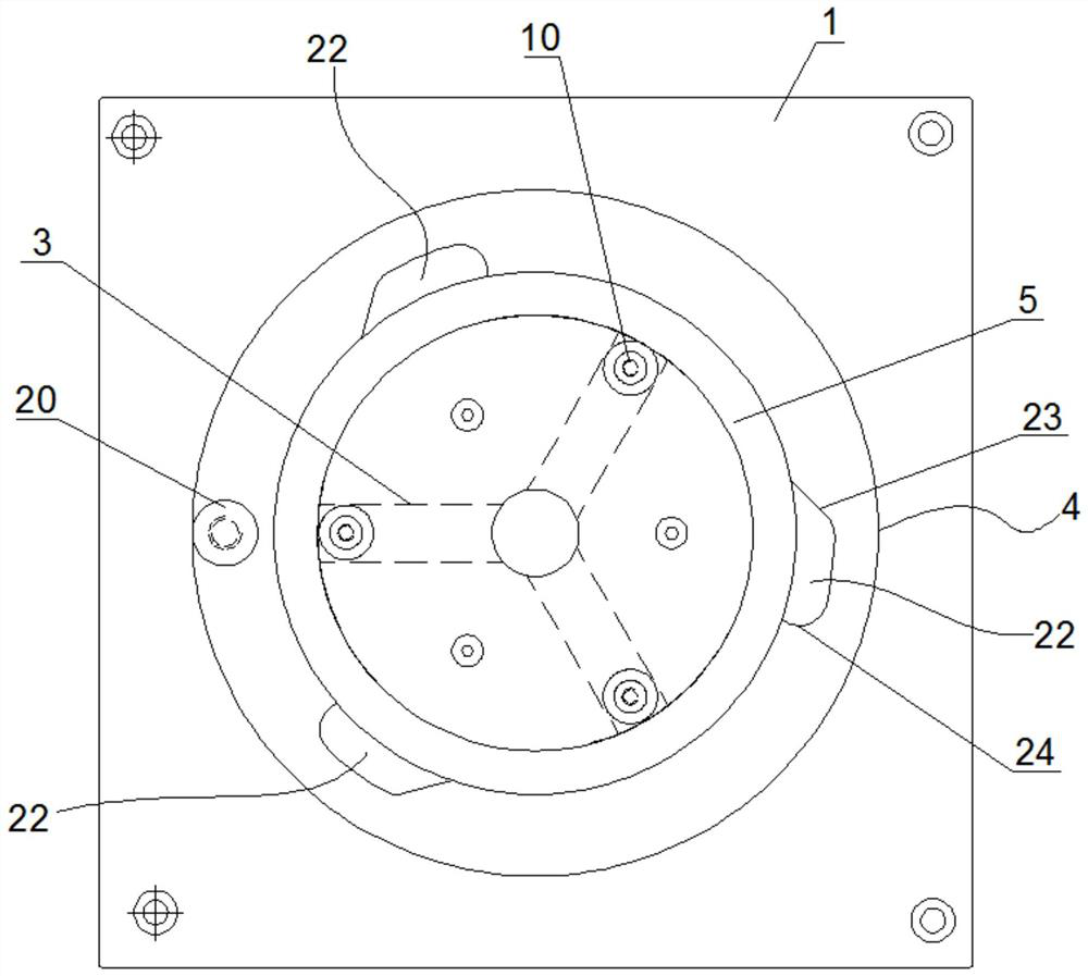
Figure 2 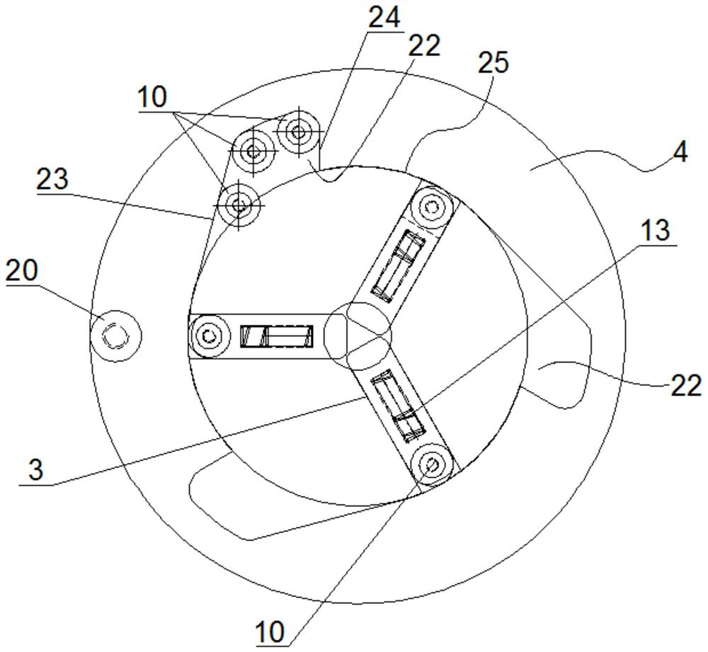
Figure 3
Abstract
Description
technical field
[0001] The invention belongs to the technical field of wire harness processing, and in particular relates to a precise axial centering device for wire harnesses. Background technique
[0002] In the wire harness processing industry, the outer diameter of the manufactured wire harness often has a certain error, and when the end face of the wire harness needs to be manufactured, it is easy to cause many quality risks in the manufacturing process. For example: when performing glue injection and waterproof treatment on the end surface of the automobile wire harness, the wire harness is usually fixed online. Due to the uncertainty of the outer diameter of the wire harness, this fixing method cannot accurately locate the axis of the wire harness, which will lead to glue injection. The unevenness will cause quality defects such as glue overflow on the surface of the wire. Due to the existence of such surface glue overflow, manual glue injection or mechanical glue i...
Examples
Embodiment Construction
[0019] The present invention will be further described below in conjunction with accompanying drawing.
[0020] Such as Figure 1 to Figure 3 As shown, a precise axial centering device for a wire harness includes a supporting fixed plate 1, a jaw seat 2, a mechanical jaw 3, a rotating sleeve 4 and a cover plate 5;
[0021] The center of the supporting and fixing plate 1 is provided with a wire hole B15;
[0022] The jaw seat 2 is fixedly connected to the center of the upper end surface of the support fixed plate 1, and the axis of the jaw seat 2 is provided with a wire-passing hole A6, and the wire-passing hole A6 and the wire-passing hole B15 are coaxially arranged; 2 A plurality of radial chute A7 is evenly opened in the circumferential direction of the upper part, and a plurality of radial chute B8 is correspondingly opened in the lower part of the plurality of radial chute A7; the radial chute A7 is a radial through groove , its two ends are respectively connected throug...