
A self-detaching sewing device for an automatic sewing system
A sewing and self-unloading technology, which is applied in the direction of sewing equipment, threading devices, sewing machine components, etc., can solve the problems of complex structure, easy failure, and defective production of tribute needle machines, so that it is not easy to produce defective products and simplify the complexity degree of effect
Patent Information
- Authority / Receiving Office
- CN · China
- Patent Type
- Patents(China)
- Current Assignee / Owner
- Publication Date
- 2021-11-26
Smart Images
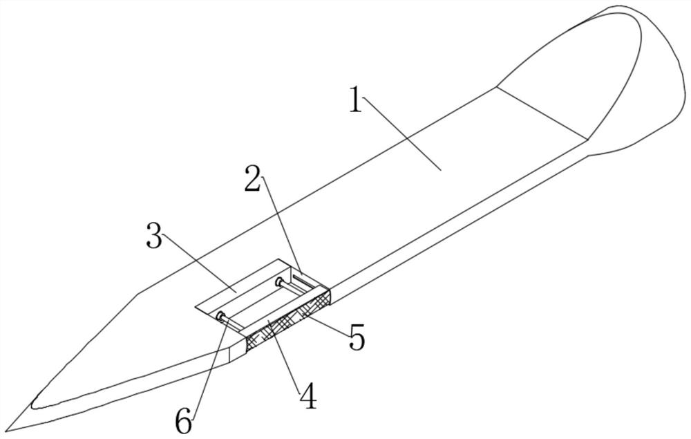
Figure 1 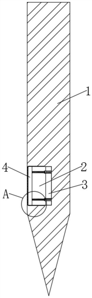
Figure 2 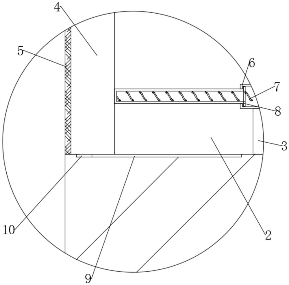
Figure 3
Abstract
Description
technical field
[0001] The invention relates to the field of sewing devices, more specifically, to a self-detaching sewing device used in an automatic sewing system. Background technique
[0002] The original meaning of textile is taken from the general term of spinning and weaving, but with the continuous development and improvement of the textile knowledge system and subject system, especially after the emergence of non-woven textile materials and three-dimensional composite weaving technologies, it is not only the traditional hand spinning And weaving, including non-woven technology, is one of the most primitive industrial technologies. Sewing refers to the weaving, sewing, embroidery and other work done by women in the old days. People are more accustomed to using the term "female worker" to refer to female workers engaged in textile, sewing, embroidery, etc. With the development of integrated circuits and the development of electronic control technology, more and more e...
Examples
Embodiment 1
[0033] see Figure 1-3, a self-detachable sewing device for an automatic suture system, including a sewing device and a suture thread, the sewing device includes a needle body 1, a movable groove 2 is dug on the side wall of the needle body 1, and the movable groove 2 is located on the needle body 1 On the needle tip side of the movable groove 2, a fixed magnetic block 3 matching itself is fixedly connected to the side wall of the movable groove 2, and an electromagnetic block 4 matching itself is slidably connected in the movable groove 2, between the electromagnetic block 4 and the side wall of the movable groove 2 A pair of telescopic tubes 6 are fixedly connected between them. The telescopic tubes 6 are divided into two parts, the movable end and the fixed end. The fixed end runs through the fixed magnetic block 3 and is fixedly connected with the side wall of the movable groove 2. 6 is plugged with a compression spring 7, the two ends of the compression spring 7 are fixed...