

A kind of electric engineering pipeline and its construction method
A construction method and technology of electric power engineering, applied in the field of electric power engineering, can solve the problems of mutual entanglement of cables and affect the efficiency of cables, and achieve the effect of reducing mutual entanglement, improving efficiency and increasing speed
Patent Information
- Authority / Receiving Office
- CN · China
- Patent Type
- Patents(China)
- Current Assignee / Owner
- Publication Date
- 2021-11-16
Smart Images
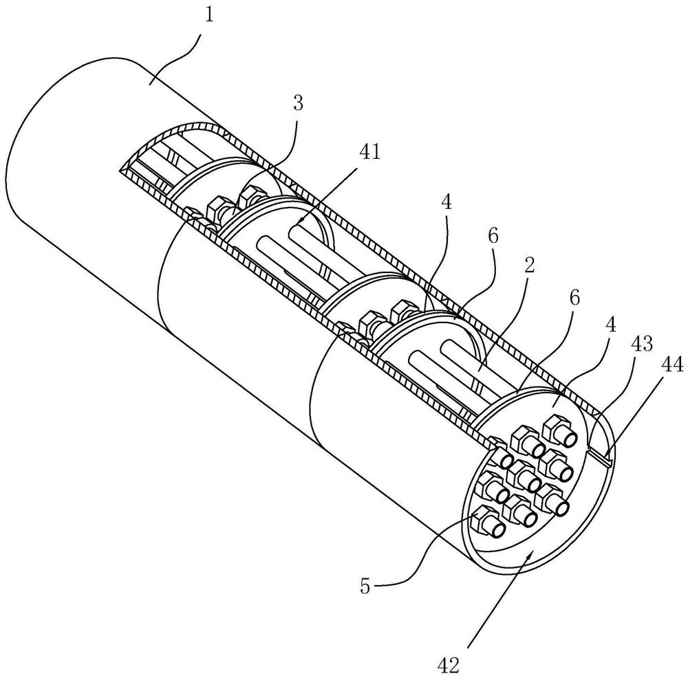
Figure 1 
Figure 2 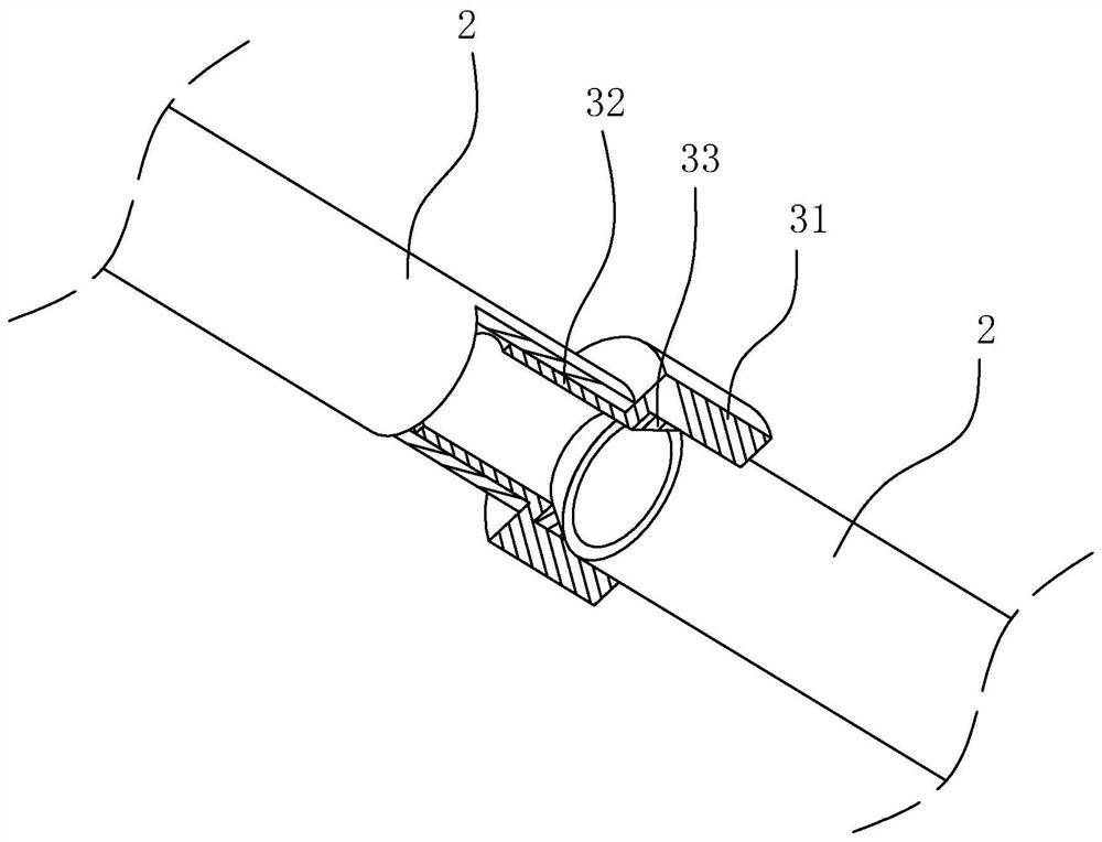
Figure 3
Abstract
Description
technical field
[0001] The present application relates to the field of electric power engineering, in particular to a power engineering pipeline and a construction method thereof. Background technique
[0002] At present, in the construction process of power engineering, cable laying is very common. When the cable needs to be laid underground, it is usually first to bury the pipeline to protect the cable underground, and then install the cable in the pipeline, and make the inside of the pipeline have good airtightness, so as to ensure that the cable in the pipeline is basically free from air and rain. erosion.
[0003] In view of the above-mentioned related technologies, the inventor believes that when laying pipelines, multiple cables are often passed through the same pipeline, and multiple cables will accumulate at the bottom of the pipeline under the action of gravity, which will cause the cables to interact with each other. The winding situation affects the efficiency ...
Examples
Embodiment Construction
[0039] The following is attached Figure 1-3 The application is described in further detail.
[0040] The embodiment of the application discloses a power engineering pipeline. refer to figure 1 A power engineering pipeline includes a dry section outer pipe 1, several groups of inner pipes 2, several connectors 3 and several installation plates 4, the number of groups of the inner pipe 2 is consistent with the number of groups of the outer pipe 1, and each section of the outer pipe 1 A group of inner tubes 2 are arranged inside, and a mounting plate 4 is provided at both ends of each section of the outer tube 1, and a plurality of perforations 41 are provided on the mounting plate 4, and one perforation 41 is used for an inner tube 2 in the outer tube 1 to pass through. By doing this, the inner tube 2 is fixed in the outer tube 1. The connecting piece 3 is arranged between the adjacent outer pipes 1 , and the connecting piece 3 communicates with the corresponding inner pipes 2...