
Convenient-to-use power cable corrector
A power cable and corrector technology, applied in the field of cable correction equipment, can solve problems such as repeated disassembly and assembly, and achieve the effects of improving the scope of application, reducing friction, and simple structural design
Patent Information
- Authority / Receiving Office
- CN · China
- Patent Type
- Applications(China)
- Current Assignee / Owner
- Publication Date
- 2021-02-09
Smart Images
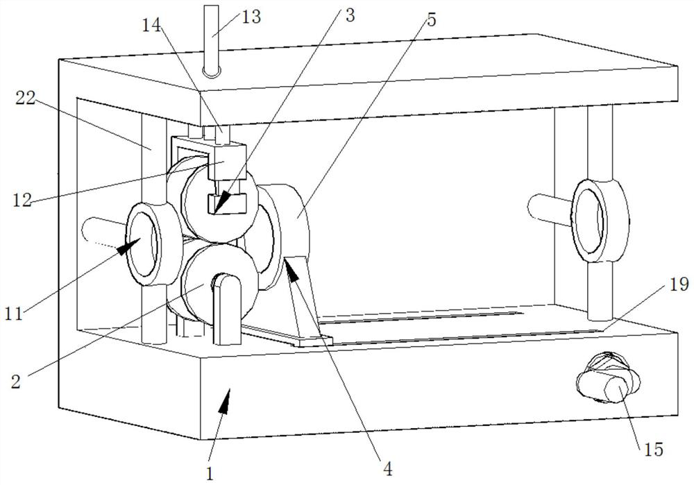
Figure 1 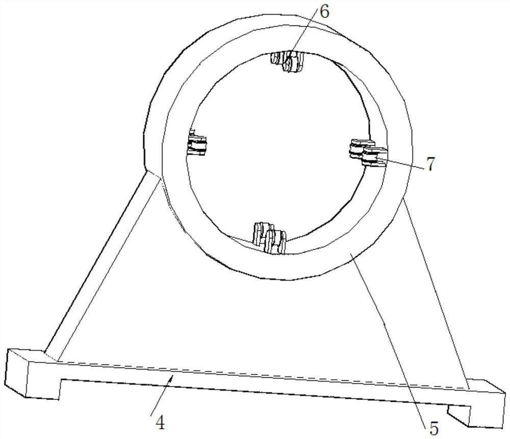
Figure 2 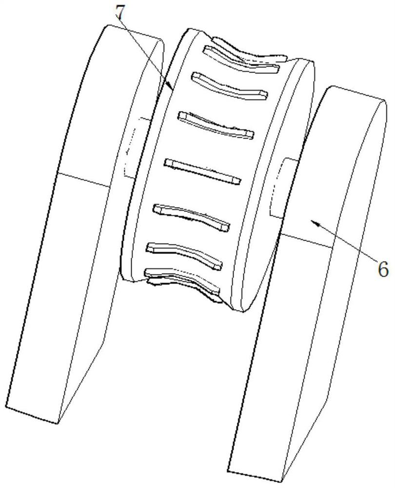
Figure 3
Abstract
Description
technical field
[0001] The invention belongs to the technical field of cable correction equipment, in particular to a convenient power cable correction device. Background technique
[0002] A cable is an electrical energy or signal transmission device, usually composed of several or several groups of wires. Because the cables are usually very long, they usually need to be curled up for transportation during transportation, which will cause the cables to bend, and the cables usually need to be kept straight when they are used. At this time, the cables need to be corrected for use. , curved cables usually cannot be used directly.
[0003] In general cable calibration equipment, after a section of cable is calibrated, the cable needs to be disassembled from the fixing device, and then the new end should be re-fixed on the equipment. time, the efficiency is very low. Contents of the invention
[0004] The invention provides an easy-to-use power cable calibrator, which is us...
Examples
Embodiment 1
[0033] An easy-to-use power cable straightener such as figure 1 As shown, it includes a base 1 with a C-shaped cross section, a fixing mechanism, a flattening mechanism and a moving structure. The flattening mechanism includes a lower pulley 2 and an upper pulley 3. One side of the base 1 is provided with a lower pulley 2, and the other Side is provided with the upper pulley 3 of adjustable position, and upper pulley 3 is corresponding with lower pulley 2 positions.
[0034] Such as figure 1 and Figure 5 As shown, one side of the upper pulley 3 is provided with a connecting frame 12, and the connecting frame 12 is provided with an adjusting rod 13 threadedly connected with the base 1; Turn the adjustment rod 13 to change the height of the connecting frame 12, and then change the distance between the upper pulley 3 and the lower pulley 4, so that it is suitable for cables of different specifications; and the adjustment rod 13 is screwed to the base 1, and is in a locked stat...
Embodiment 2
[0044] On the basis of Example 1, such as Figure 7 As shown, the moving structure further includes a telescopic rod 20 and a connecting block 21 , the telescopic rod 20 is provided on the lower side of the sliding seat 4 , and the other side of the telescopic rod 20 is movably connected to the connecting block 21 located on the side of the conveyor belt 18 . The connecting block 21 is always connected with the telescopic rod 20 when the conveyor belt 18 moves, and the user can turn the handle in one direction to realize the reciprocating movement of the slide seat 4, so as to move the cable from the flattening mechanism to the other side, which is convenient to use.
[0045] There are two sets of pawls 10 on the runner 7 , one set of pawls 10 is located in the wheel groove 8 , and the other set of pawls 10 is located between the outer side of the wheel groove 8 and the friction wheel 7 . One set of pawls cooperates with the wheel groove 8 to form a ratchet pawl structure, so ...