
Upper-layer motion state control method for four-hub motor-driven vehicle
A control method and technology of in-wheel motors, which are applied in electric vehicles, control drives, control devices, etc., can solve the influence of steering stability without considering the side slip angle of the center of mass, the lack of joint control of the side slip angle of the center of mass and the yaw rate, tire Model accuracy requirements are too high, etc.
Patent Information
- Authority / Receiving Office
- CN · China
- Patent Type
- Applications(China)
- Current Assignee / Owner
- Publication Date
- 2021-02-19
Smart Images
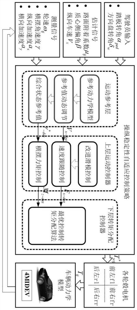
Figure 1 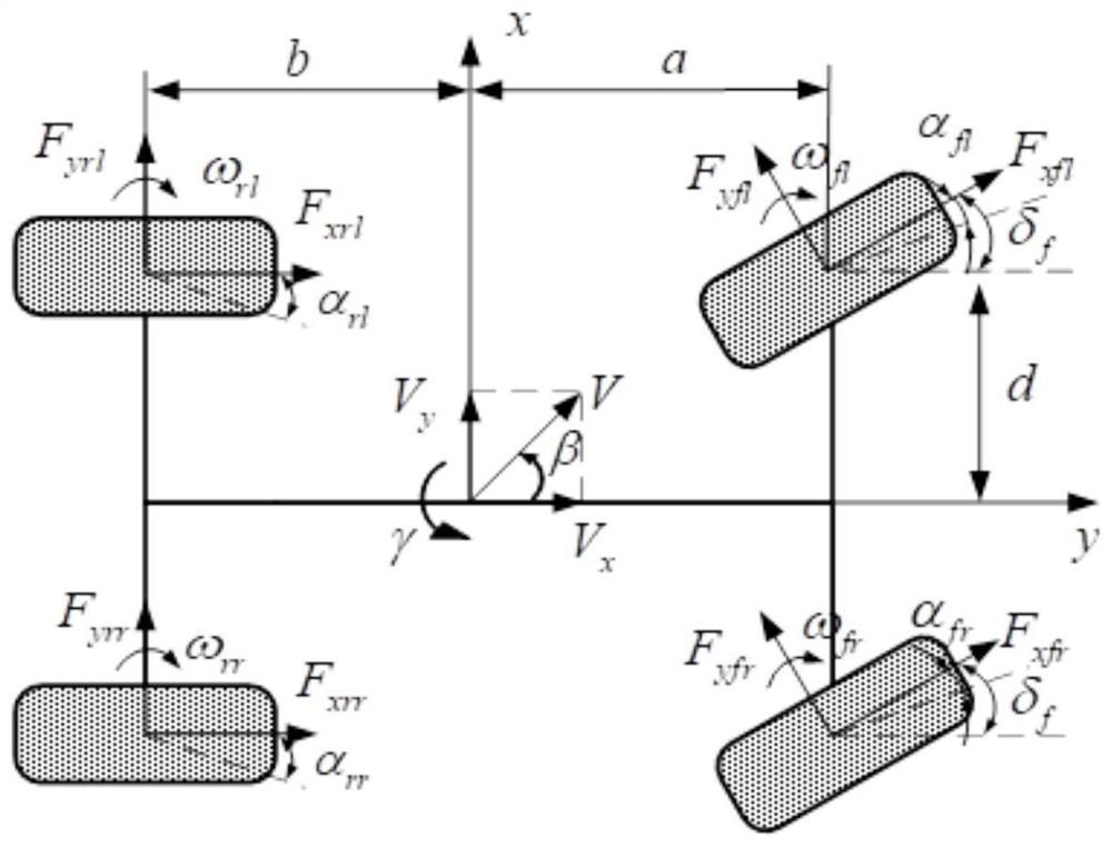
Figure 2 
Figure 3
Abstract
Description
technical field
[0001] The invention relates to the technical field of distributed drive vehicle control, in particular to a control method for realizing stable maneuvering of a four-wheel-hub motor-driven vehicle under road conditions with different adhesion coefficients and variable adhesion coefficients. Background technique
[0002] The driving / braking torque of the four driving wheels of the four-wheel hub motor drive vehicle can be independently controlled, which is more conducive to the realization of steering stability control during the steering process. At present, the direct yaw moment control (DYC) is mostly used for the steering stability control of in-wheel motor driven vehicles, which can achieve good stability control effects in both linear and nonlinear working areas of tires. DYC-based handling and stability control strategies mainly have two control structures: integrated control and hierarchical control. Among them, hierarchical control mainly includes u...
Examples
Embodiment Construction
[0108] The technical solutions of the present invention will be clearly and completely described below in conjunction with the accompanying drawings. Apparently, the described embodiments are some of the embodiments of the present invention, but not all of them. Based on the embodiments of the present invention, all other embodiments obtained by persons of ordinary skill in the art without making creative efforts belong to the protection scope of the present invention.
[0109] A method for controlling the motion state of the upper layer of a four-wheel hub motor driven vehicle provided by the present invention, such as figure 1 As shown, it specifically includes the following steps:
[0110] Step 1. For a vehicle driven by four-wheel hub motors, a seven-degree-of-freedom vehicle dynamics model including longitudinal, lateral, yaw and four wheel rotation degrees of freedom is established; the specific form of the model is as follows figure 2 shown;
[0111] Step 2. Determin...