
Cooling device for aeroengine turbine guide vane
A turbine guide, aero-engine technology, applied in engine components, machines/engines, mechanical equipment, etc., can solve problems such as limited air heat dissipation capacity, and achieve the effects of reducing instability, increasing combustion efficiency, and improving strength
Patent Information
- Authority / Receiving Office
- CN · China
- Patent Type
- Patents(China)
- Current Assignee / Owner
- Publication Date
- 2022-06-28
Smart Images
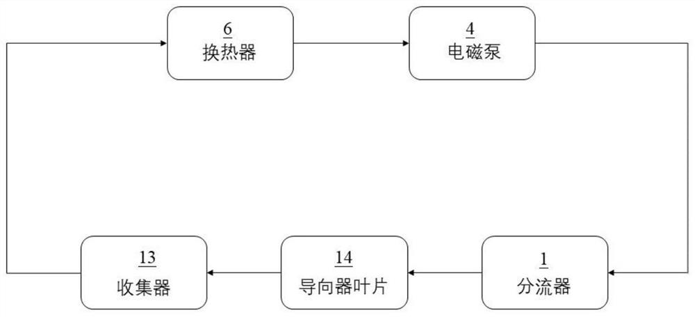
Figure 1 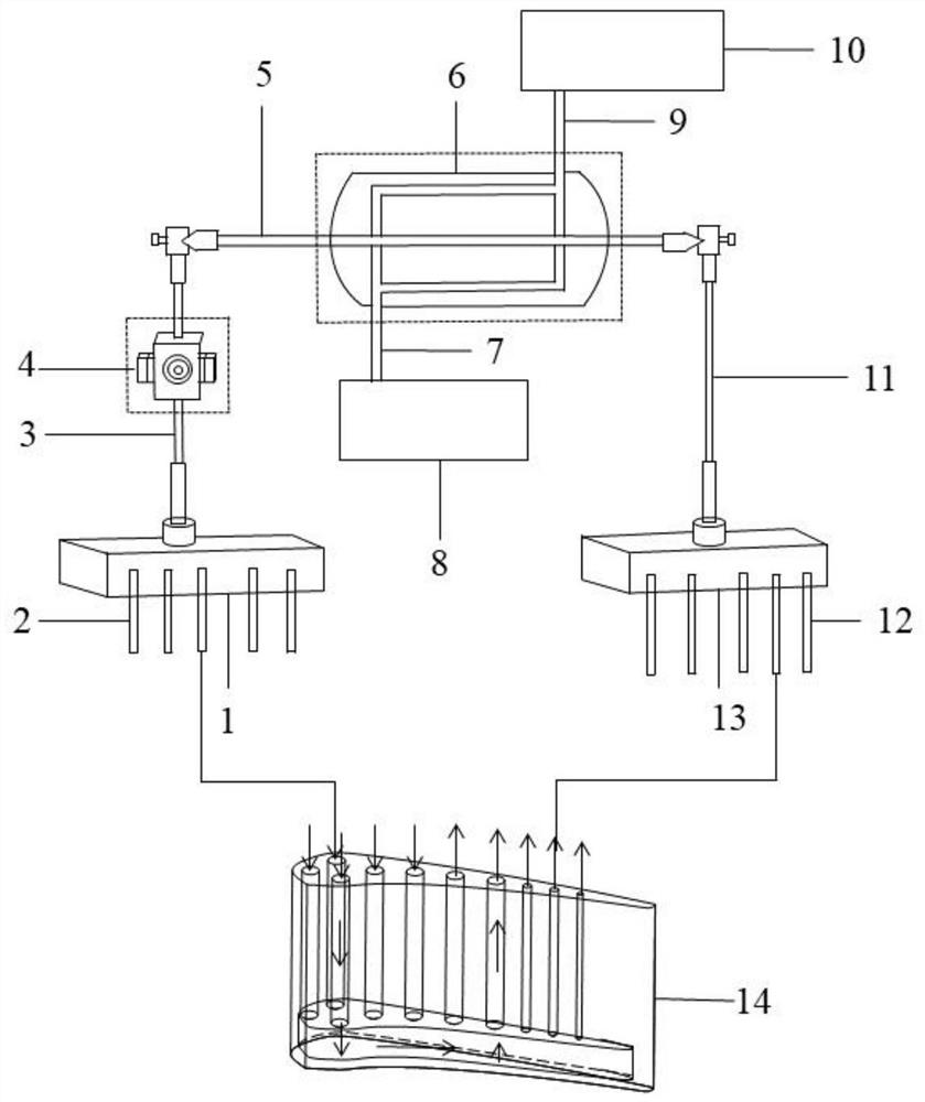
Figure 2 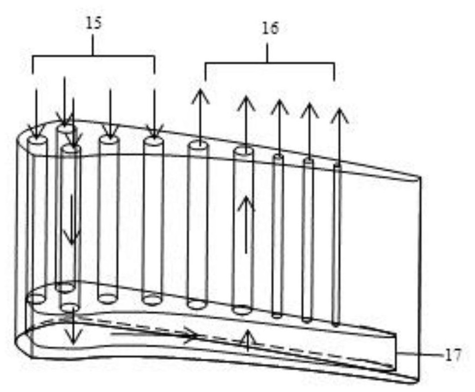
Figure 3
Abstract
Description
technical field
[0001] The present application relates to aero-engine turbine guide vanes, and in particular, to a cooling device for aero-engine turbine guide vanes. Background technique
[0002] As the "heart" of the aircraft, the aero-engine is known as the "jewel in the industrial crown", and its performance indicators directly affect the safety, reliability and economy of the aircraft. In the development of aviation gas turbine engines, in order to improve the thermal efficiency and thrust-weight ratio of the engine, the boost ratio of the compressor and the inlet temperature of the turbine have been continuously increased. The engine with a thrust-to-weight ratio of 10 in the fourth-generation fighter has a compressor boost ratio of over 30, and the temperature before the turbine is close to 2000K. It is expected that a fighter engine with a thrust-to-weight ratio of more than 20 may appear around 2030. Compared with the F119 engine, the fuel consumption rate is reduc...
Examples
Embodiment Construction
[0032] figure 1 is a schematic logic control diagram of a cooling device for a turbine guide vane of an aero-engine according to an embodiment of the present application. figure 2 It is a schematic structural diagram of a cooling device for aero-engine turbine guide vanes. image 3 is a schematic perspective view of the guide vane.
[0033] like image 3 As shown, in this embodiment, a plurality of cooling channels are arranged in the guide vane 14 according to the airfoil shape. A cavity 17 is reserved at the bottom position within the guide vane 14 . Each cooling channel communicates with the chamber 17 . Part of the cooling passages in the plurality of cooling passages are inflow blade cooling passages 15 , and the remaining cooling passages in the plurality of cooling passages are outflow blade cooling passages 16 . like figure 1 shown, see also Figure 2-3, this embodiment provides a cooling device for aero-engine turbine guide vanes using a low melting point meta...