
Dynamic balance mechanical plane rotary valve
A plane-rotating, mechanical technology, used in sliding valves, mechanical equipment, engine components, etc., can solve problems such as high assembly accuracy requirements and liquid leakage, and achieve the effect of meeting elastic requirements, improving service life, and ensuring stability.
Patent Information
- Authority / Receiving Office
- CN · China
- Patent Type
- Applications(China)
- Current Assignee / Owner
- Publication Date
- 2021-06-29
Smart Images
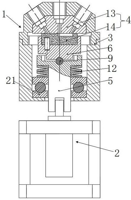
Figure 1 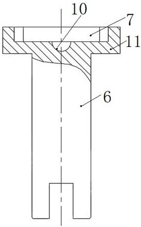
Figure 2 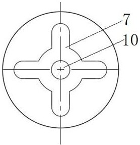
Figure 3
Abstract
Description
technical field
[0001] The invention relates to the technical field of valve bodies, in particular to a dynamic balance mechanical plane rotary valve. Background technique
[0002] At present, in industries such as environmental protection on-line monitoring instruments and medical equipment, mechanical flat rotary valves are widely used as a means of liquid diversion to switch and sample various liquids. When this type of mechanical flat rotary valve is working, two working The planes must be fitted in parallel at any angle, so that the mechanical plane rotary valve will not leak liquid under a certain working pressure.
[0003] The mechanical plane rotary valve currently used in the market is difficult to ensure that the two working surfaces of the mechanical plane rotary valve are parallel to the axial plane due to the shape and position tolerances of various related parts during the processing process and the cumulative error in the assembly process. Fitting, resulting ...
Examples
Embodiment Construction
[0035] The present invention will be more clearly and completely described below by way of a preferred embodiment with reference to the accompanying drawings, but the present invention is not limited to the scope of the described embodiment.
[0036] Such as figure 1 Shown is a dynamic balance mechanical planar rotary valve provided by the present invention, including a valve body 1 and a driving device 2, the valve body 1 includes a housing 3 and a valve core 4, the valve core 4 is arranged in the housing 3, and the valve core 4 is connected with the driving end of the driving device 2 through a coupling assembly.
[0037] The coupling assembly includes a rotating shaft 5 and a rotating sleeve 6. The rotating sleeve 6 and the valve core 4 are all on the axis of the rotating shaft 5. The rotating sleeve 6 is connected to the rotating shaft 5 and the valve core 4. The other end of the rotating shaft 5 is connected to the drive device 2. The transmission end is slidingly connec...