
A conveying and metering device for powder auxiliaries used in the printing and dyeing industry
A metering device and powder technology, which is applied in the direction of measuring devices, conveying bulk materials, conveyors, etc., can solve the problems of low work efficiency, heavy labor, and low metering accuracy, and achieve the goal of improving metering accuracy and work efficiency Effect
Patent Information
- Authority / Receiving Office
- CN · China
- Patent Type
- Patents(China)
- Current Assignee / Owner
- Publication Date
- 2022-07-12
Smart Images
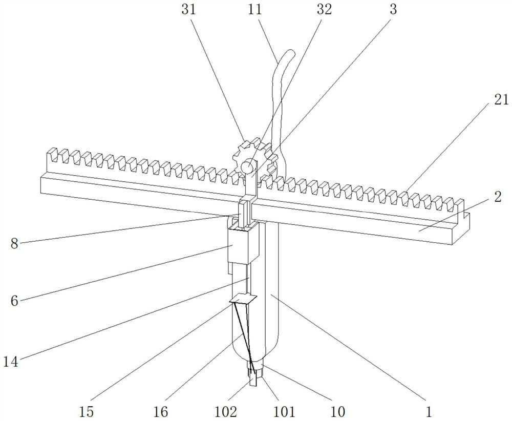
Figure 1 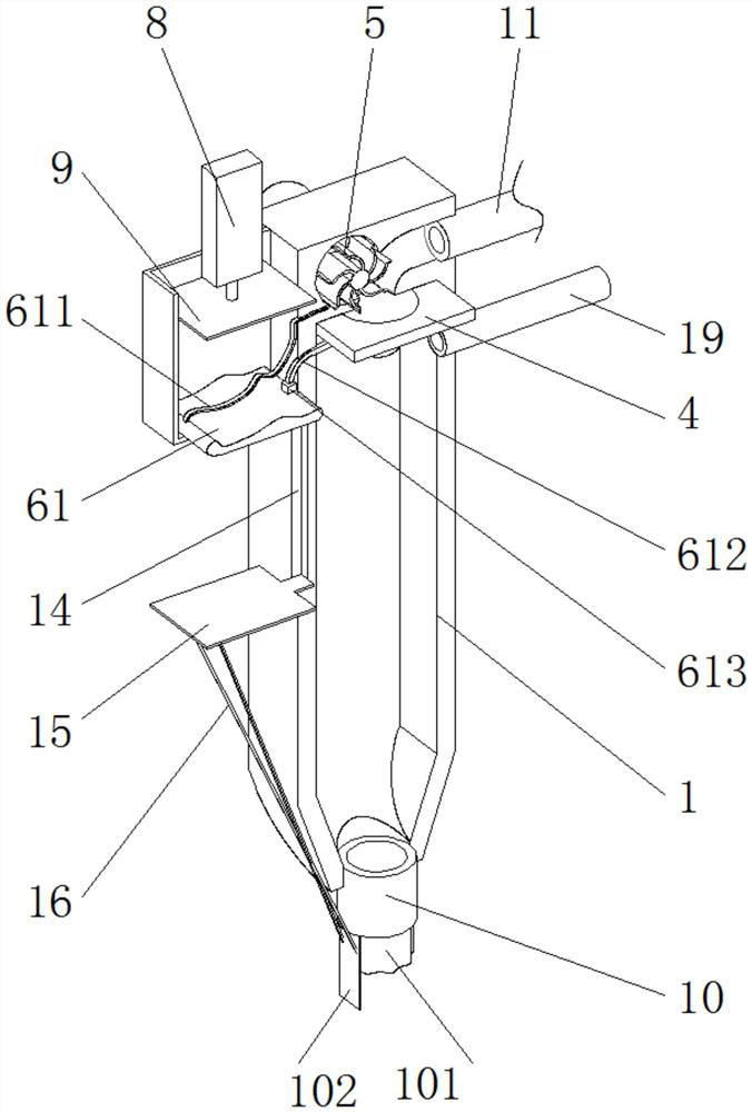
Figure 2 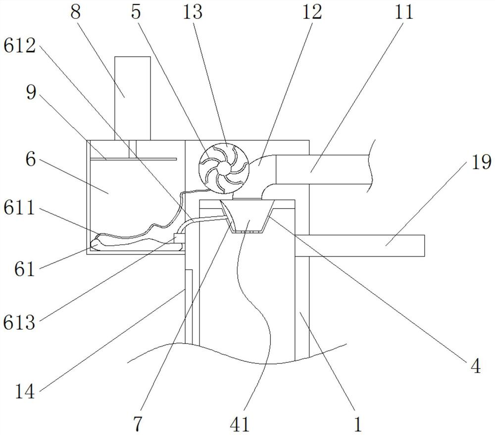
Figure 3
Abstract
Description
technical field
[0001] The invention relates to the technical field of printing and dyeing equipment, in particular to a conveying and metering device for powder auxiliaries used in the printing and dyeing industry. Background technique
[0002] In the process of large-scale dye vat production, the powder auxiliaries required by each dye vat must be transported to the transition bin on each dye vat bucket, and after accurate measurement, the transition bin is transported to the dye vat vat.
[0003] In the prior art, manual transportation is used for measurement. Although manual transportation has no energy consumption and is easy to control the bath ratio, it has a large amount of labor and low work efficiency, and wastes a lot of materials during measurement, and the measurement accuracy is low. The probability of work injury is very undesirable.
[0004] Therefore, those skilled in the art need to develop a conveying metering device with fast conveying speed, accurate me...
Examples
Embodiment Construction
[0028] The embodiment of the present invention provides a conveying and metering device for powder auxiliaries used in the printing and dyeing industry, such as Figure 1-8 As shown, the powder additives are metered. It includes an injection chamber 1, the back of the injection chamber 1 is welded with an air pipe 11, an air guide groove 12 is opened inside the injection chamber 1, and the air pipe 11 is communicated with the air guide groove 12. An isolation plate 4 is welded in the injection chamber 1 , and the isolation plate 4 is located below the air guide groove 12 . A feed pipe 19 is welded on the back of the injection chamber 1 , and the feed end of the feed pipe 19 is located below the isolation plate 4 . A nozzle 10 is fixedly installed at the bottom of the injection chamber 1 , and a depression 41 is formed on the isolation plate 4 relative to the air guide groove 12 , and a plurality of leak holes 42 are formed in the depression 41 .
[0029] A cavity 13 is opene...