
Bullet wound dressing change device
A technology for wounds and bullets, which is applied in the field of dressing change devices for bullet wounds, which can solve the problems of poor dressing of wounds, and achieve the effect of convenient connection belt length, simple operation, and easy dressing dressing
Patent Information
- Authority / Receiving Office
- CN · China
- Patent Type
- Applications(China)
- Current Assignee / Owner
- Publication Date
- 2021-07-23
Smart Images
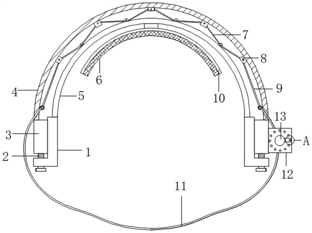
Figure 1 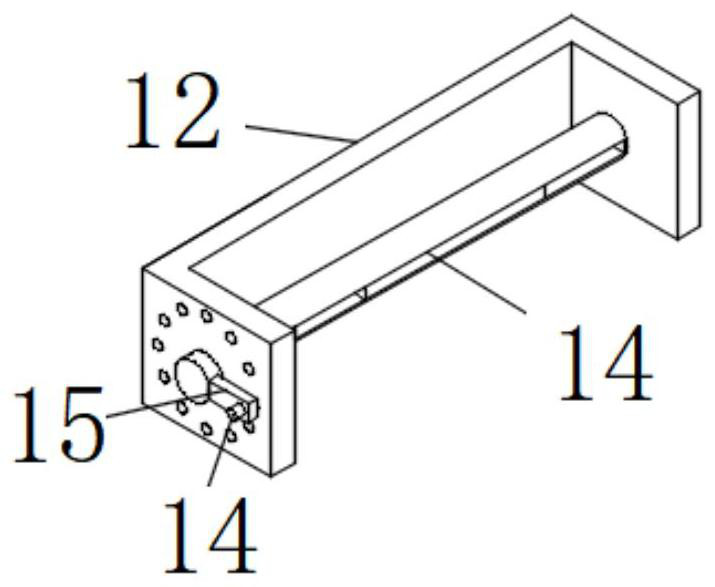
Figure 2 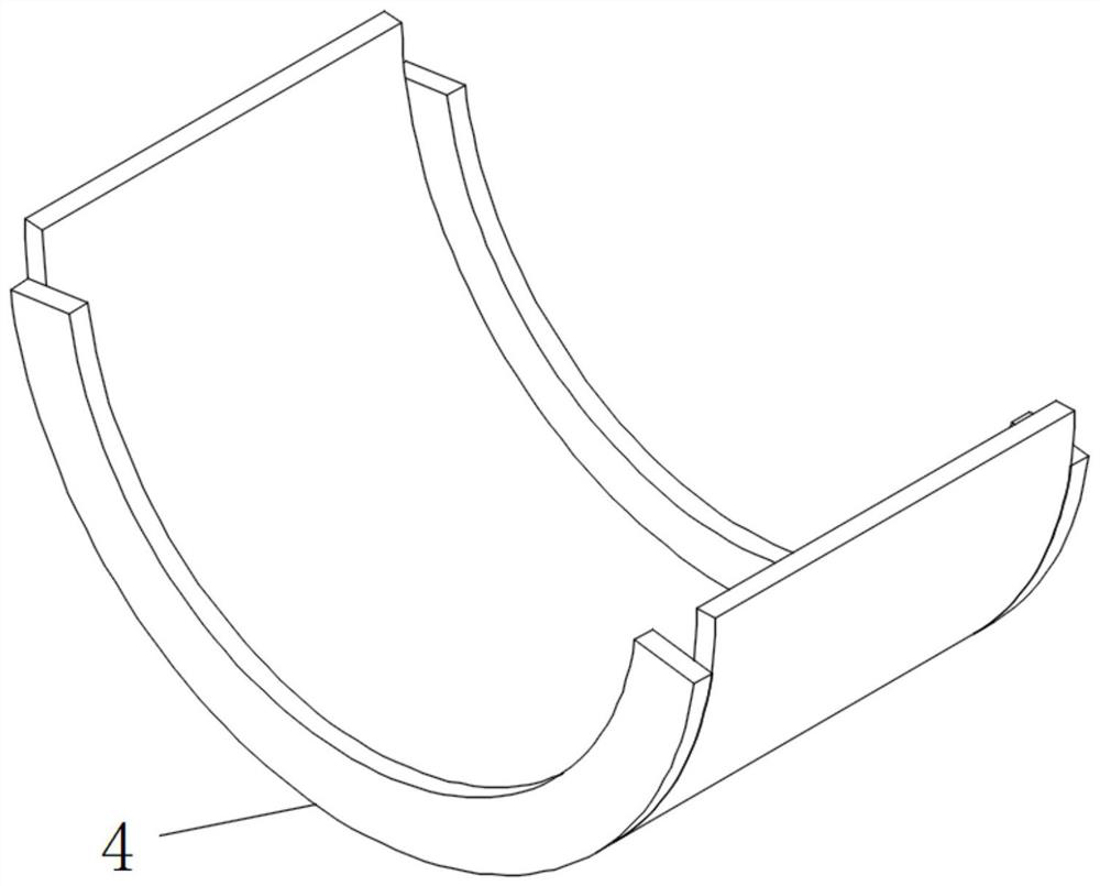
Figure 3
Abstract
Description
technical field
[0001] The invention relates to the technical field of changing dressings for bullet wounds, in particular to a device for changing dressings for bullet wounds. Background technique
[0002] For gunshot wounds, after the bullet hits the human body, all the kinetic energy is often released. The specific performance is that the bullet is severely deformed or even ruptured, resulting in a trumpet-shaped cavity in the human tissue. The wound area is hundreds of times the cross-sectional area of the bullet. The damage caused by the huge pressure of the blood circulation system in the blood circulation system. Generally, after a single soldier is wounded by a gun in field combat, there is a problem that the wound is not well bandaged. Therefore, we have proposed a dressing change device for bullet wounds. Contents of the invention
[0003] The device for changing dressings for gunshot wounds proposed by the invention solves the problem of poor bandaging of woun...
Examples
example
[0018] refer to Figure 1-4 , an example provided by this scheme: a device for changing dressings for bullet wounds, including a first arc-shaped spring plate 4 and a second arc-shaped spring plate 5, and the front and back sides of the first arc-shaped spring plate 4 are symmetrically arranged with multiple A fixed block 8, a supporting tensioning device is hinged between two adjacent fixed blocks 8 on the same side, the bottom outer wall of the second arc spring plate 5 is fixedly provided with a wound fixation device, and the bottom of the second arc spring plate 5 The L plate 1 is symmetrically fixedly connected, and the bottom of the first arc spring plate 4 is symmetrically fixedly connected with a rectangular sleeve 3, and the outside of the rectangular sleeve 3 is slidingly connected with the L plate, and the supporting and tensioning device includes two same ends hinged to each other The connecting rod 7, the other end of the connecting rod 7 is hinged with the fixed ...