
Device and method for adjusting and replacing swing sensor of hydraulic turbine set on line
A sensor and unit technology, applied in the direction of machines/engines, hydropower, mechanical equipment, etc., can solve the problem that the online monitoring system of the unit cannot correctly reflect the swing data, and affects the operation and maintenance personnel on the operation status of the unit.
Patent Information
- Authority / Receiving Office
- CN · China
- Current Assignee / Owner
- Publication Date
- 2021-10-22
Smart Images
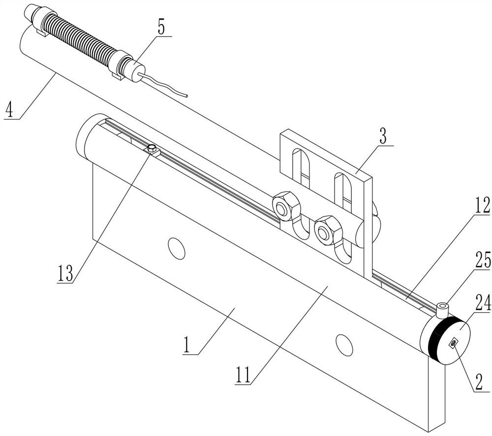
Figure 1 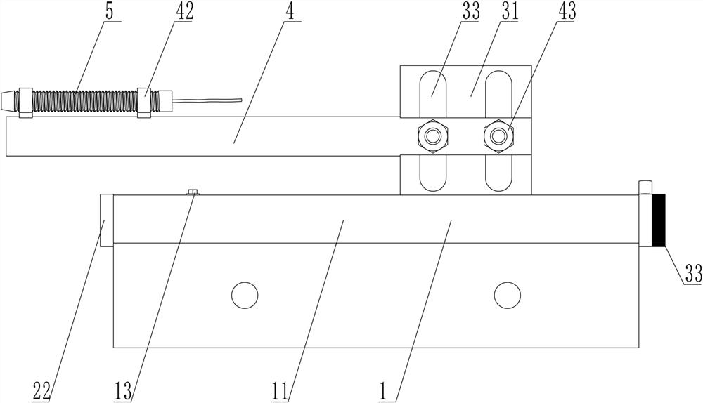
Figure 2 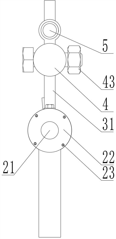
Figure 3
Abstract
Description
technical field
[0001] The invention belongs to the technical field of on-line monitoring of water turbines, and relates to a device and method for online adjustment and replacement of a swing sensor of a water turbine unit. Background technique
[0002] The installation of the swing sensor of the turbine must be completed before the operation of the unit, and the clearance adjustment between the swing sensor and the main shaft of the turbine must be completed. The current problem is that once the unit finds that the gap value is incorrect or the swing sensor fails during operation, it must be adjusted or replaced after the unit is shut down, which leads to the fact that the unit’s online monitoring system cannot correctly reflect the swing during the unit’s operation. The data affects the correct judgment of the operation and maintenance personnel on the operating status of the unit. Contents of the invention
[0003] The technical problem to be solved by the present inv...
Examples
Embodiment Construction
[0040] like Figure 1~Figure 7 Among them, a device for online adjustment and replacement of the swing sensor of a water turbine unit, which includes a fixed plate 1, an adjustment mechanism 2, a bracket 3, a mounting rod 4, and a swing sensor 5; the bushing 22 of the adjustment mechanism 2 is located on the fixed plate The two ends of the guide tube 11 of 1 cooperate with it, the guide rod 21 cooperates with the shaft sleeve 22, the bracket 3 cooperates with the guide rod 21 and is limited by the guide tube 11, the installation rod 4 is connected with the bracket 3 and the swing sensor 5; the guide rod 21 rotates and drives the bracket 3 drives the swing sensor 5 to move axially along the guide tube 11. The structure is simple, the adjustment mechanism 2 is connected with the fixed plate 1, the bracket 3 cooperates with the guide rod 21 of the adjustment mechanism 2, the installation rod 4 is connected with the bracket 3 and the swing sensor 5, the limit groove 12 and the lim...