
A kind of regenerated protein cellulose fiber preparation drying treatment machine
A technology of cellulose fiber and regenerated protein, applied in progressive dryers, dryers, drying solid materials, etc., can solve the problems of reducing the drying rate of fibers, reducing the looseness of fibers, and the inability to dry fibers, etc., to achieve Increase the degree of looseness, increase the gap, and increase the effect of the speed
Patent Information
- Authority / Receiving Office
- CN · China
- Patent Type
- Patents(China)
- Current Assignee / Owner
- Publication Date
- 2022-05-13
Smart Images
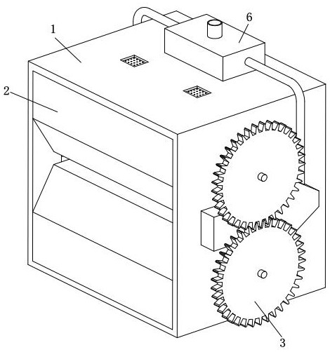
Figure 1 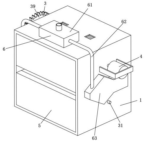
Figure 2 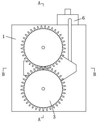
Figure 3
Abstract
Description
technical field
[0001] The invention relates to the technical field of fiber preparation and production, in particular to a machine for preparing and drying regenerated protein cellulose fibers. Background technique
[0002] Regenerated protein cellulose fiber is a category of man-made fiber, which refers to the fiber made from protein extracted from natural things such as milk, soybeans, peanuts, and corn, and dissolved in an appropriate solvent; fiber production includes oiling , Opening, washing, drying and weighing etc.
[0003] At present, the existing machinery usually has the following deficiencies when drying regenerated protein cellulose fibers: 1. The existing regenerated protein cellulose fibers usually use rolling transmission to transmit the fibers. The fiber is dried by hot air to achieve the purpose of drying, but using this method will prevent the hot air from directly drying the internal fiber, thereby reducing the drying rate of the fiber; 2. The existing ...
Examples
Embodiment Construction
[0031] The embodiments of the present invention will be described in detail below with reference to the accompanying drawings, but the present invention can be implemented in many different ways defined and covered by the claims.
[0032] refer to Figure 1-Figure 4 , a drying treatment machine for preparing regenerated protein cellulose fibers, including a drying box 1, a limit block 2, a pulling device 3, a driving motor 4, a barrier device 5 and an air intake device 6, and the drying box 1 has a rectangular structure , the inner wall of the drying box 1 is symmetrically installed with two limit blocks 2 up and down near the left end, and the right side of the two limit blocks 2 is provided with a pulling device 3, and the pulling device 3 is connected with the drying box 1. The device 3 is distributed symmetrically up and down. The output shaft of the driving motor 4 is installed at the rear end of the upper pulling device 3 on the drying box 1. The driving motor 4 is fixed...