
Heat insulation strip high-temperature bending device and using method
A technology of bending device and heat insulation strip, which is applied in the direction of feeding device, positioning device, storage device, etc., can solve the problems of low processing efficiency, broken heat insulation strip, poor plastic processing flexibility, etc. Maintenance costs, preventing damage to the insulation strip structure, and saving the area occupied by the site
Patent Information
- Authority / Receiving Office
- CN · China
- Patent Type
- Applications(China)
- Current Assignee / Owner
- Publication Date
- 2022-05-31
Smart Images
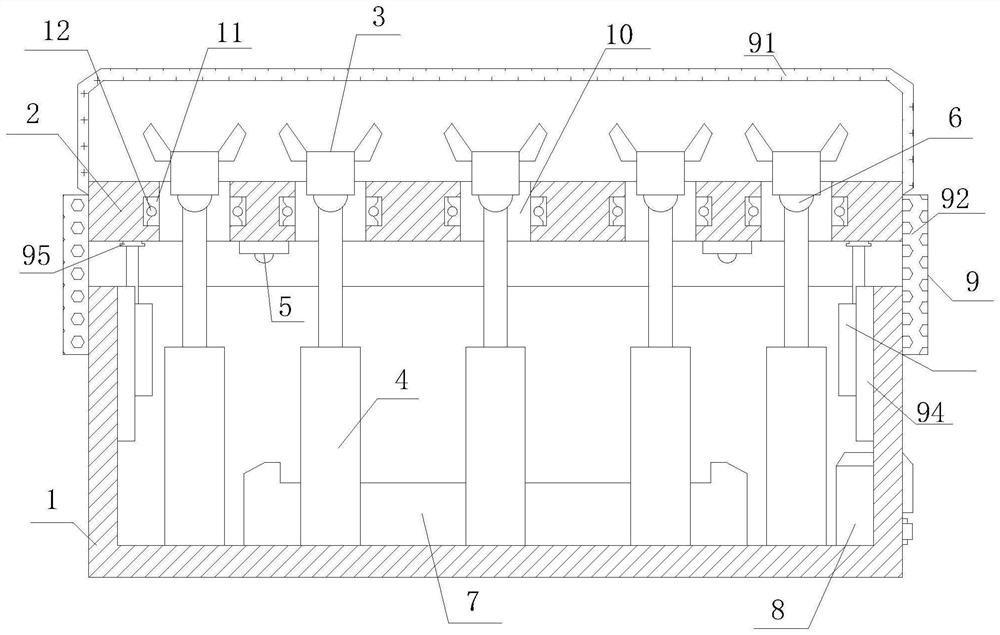
Figure 1 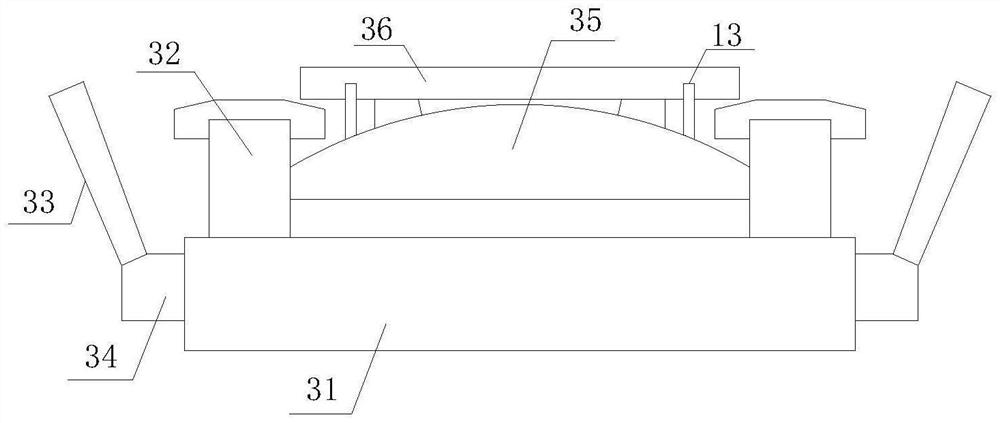
Figure 2 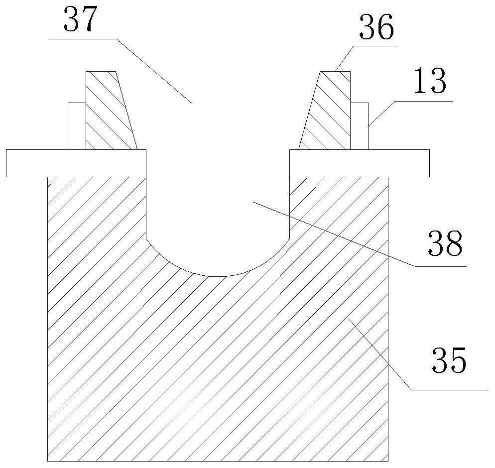
Figure 3
Abstract
Description
technical field
[0001] The invention relates to a high-temperature bending device and a use method of a heat insulation strip, and belongs to the technical field of mechanical processing equipment. Background technique
[0002] During the processing and production of door and window products and curtain wall products, it is necessary to set corresponding heat insulation strips in the door and window structure. Therefore, the heat insulation strip structure needs to be adjusted and set synchronously with the door and window structure, and the currently used heat insulation strip products are often straight lines. Therefore, it is necessary to carry out corresponding molding processing on the structure of the thermal insulation strip during use. For this processing operation, the current method is mainly to heat the thermal insulation strip by bending and shaping the thermal insulation strip directly by external force or using heating equipment such as a spray gun to heat the t...
Examples
Embodiment Construction
[0025] In order to facilitate the construction of the technical means, creation features, achievement goals and effects realized by the present invention, the present invention will be further described below with reference to the specific embodiments.
[0026] see figure 1, a high-temperature bending device for heat insulation strips, comprising a bearing base 1, a workbench 2, a positioning plastic block 3, a lifting drive mechanism 4, a temperature sensor 5, a heating mechanism 7 and a drive circuit 8, the upper end surface of which passes through the adjustment mechanism 9 It is hinged with the lower end surface of the workbench 2, and the upper end surface of the workbench 2 is at an angle of 0°-90° with the horizontal plane. The workbench 2 is a plate-like structure with a rectangular cross-section. , and each adjusting groove 10 is provided with a number of positioning plastic blocks 3 that are evenly distributed along the axis of the adjusting groove 10, each positioni...