
Permanent magnet biased inner rotor radial magnetic bearing
A technology of permanent magnet bias and magnetic bearings, applied in the direction of bearings, shafts and bearings, mechanical equipment, etc., can solve the problems of serious coupling of radial magnetic bearings, multiple magnetomotive forces, large excitation currents, etc., to ensure the stability of operation , save the control circuit, reduce the effect of axial size
Patent Information
- Authority / Receiving Office
- CN · China
- Patent Type
- Patents(China)
- Current Assignee / Owner
- Publication Date
- 2006-10-11
- Estimated Expiration
- Not applicable · inactive patent
Smart Images
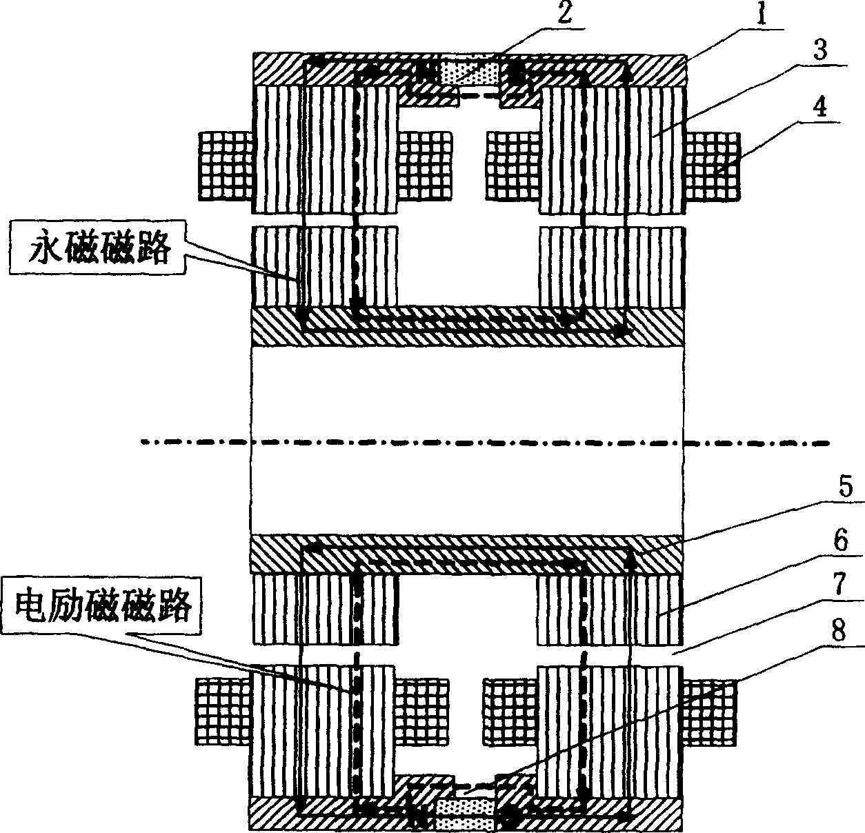
Figure 1 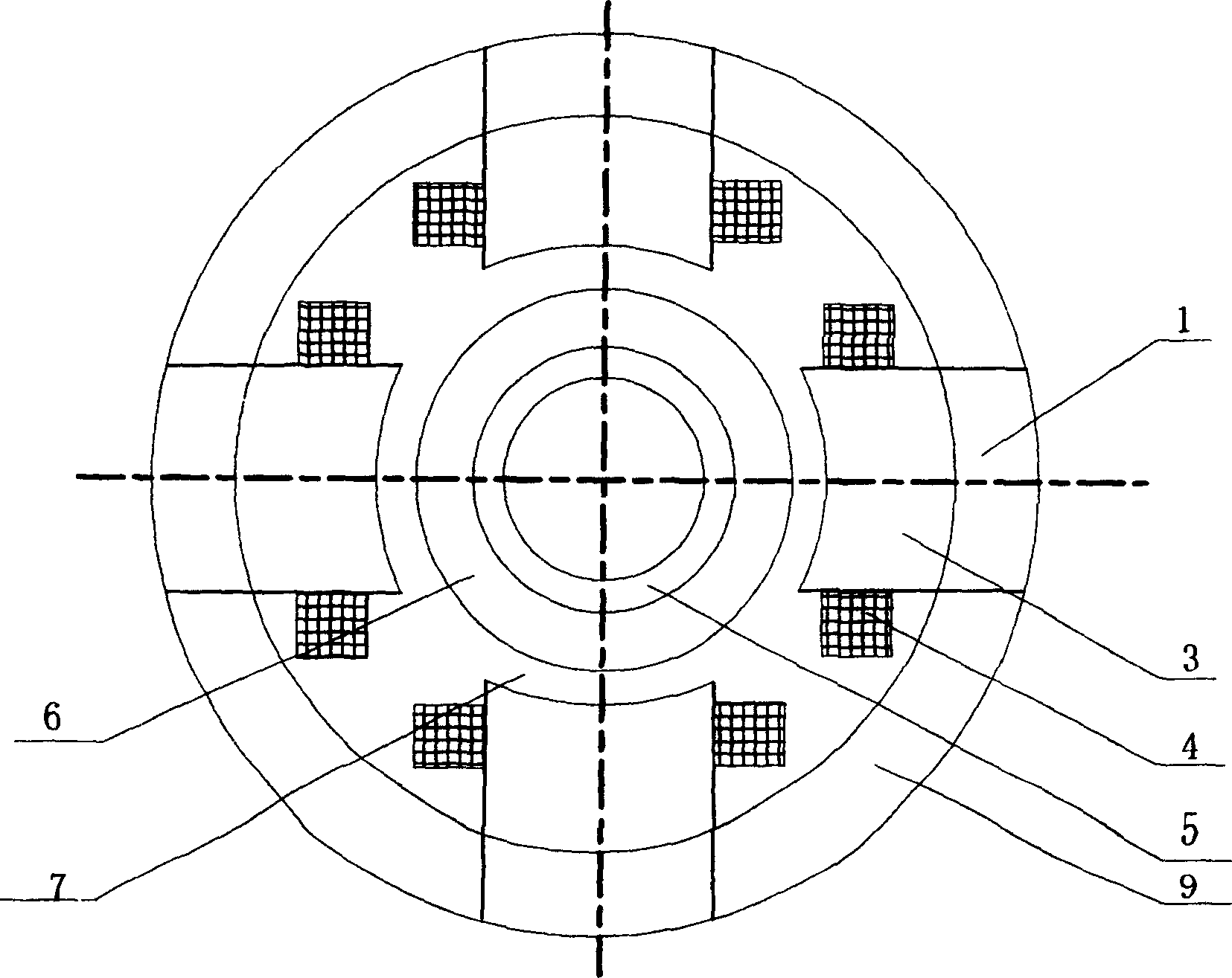
Figure 2 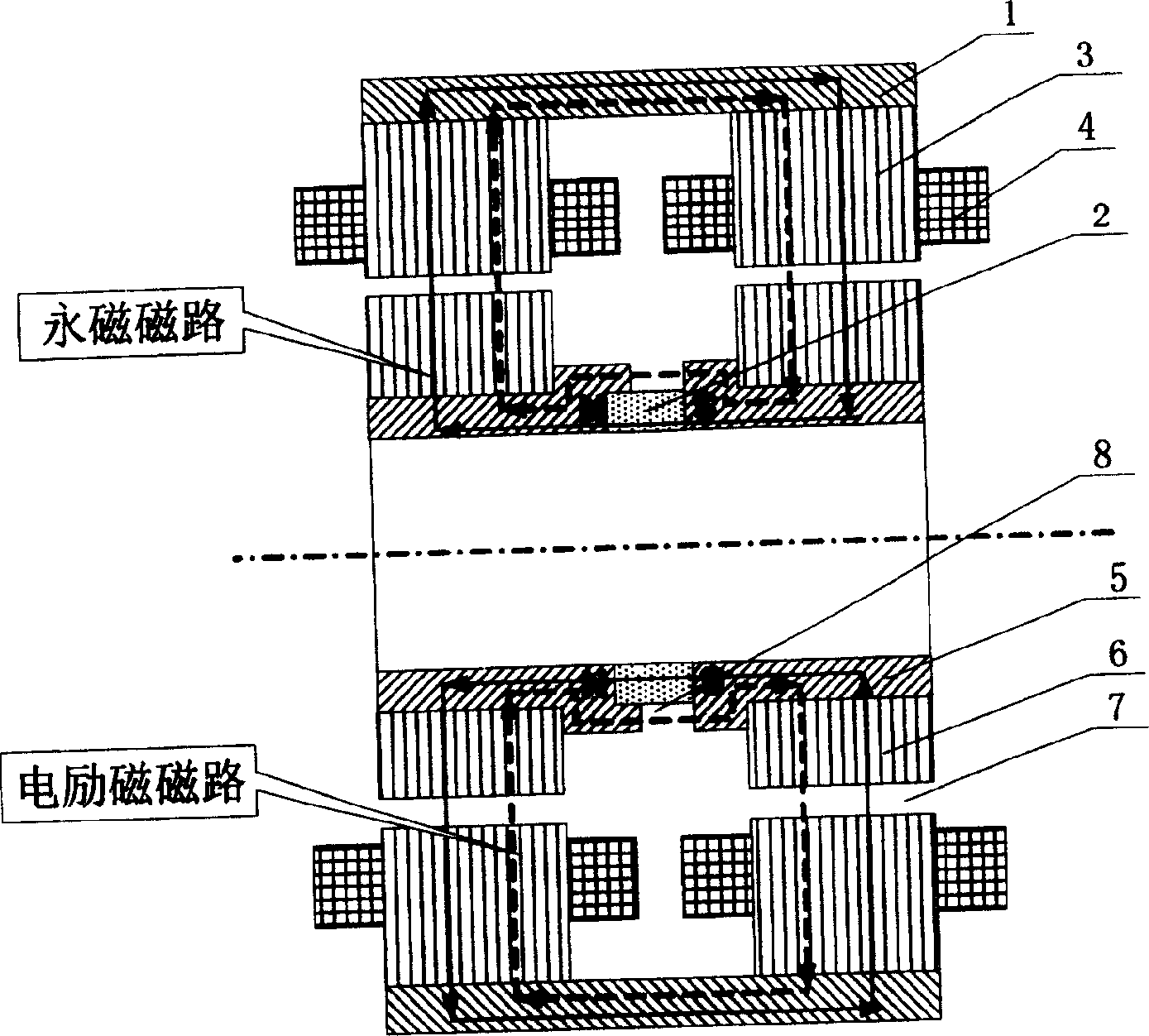
Figure 3
Abstract
Description
Technical field
[0001] The invention relates to a non-contact magnetic suspension bearing, in particular to a permanent magnetic bias inner rotor radial magnetic bearing, which can be used as a non-contact support for rotating parts in mechanical equipment such as motors and machine tools. Background technique
[0002] Magnetic suspension bearings are divided into pure electromagnetic bearings and hybrid magnetic suspension bearings with permanent magnetic bias and electromagnetic control. The former uses large current and consumes a lot of power, and the hybrid magnetic suspension bearings with permanent magnetic bias and electromagnetic control. The magnetic field generated by the permanent magnet bears the main load. Bearing capacity, the electromagnetic field provides auxiliary adjustment bearing capacity, so this kind of bearing can greatly reduce the control current and reduce the loss. However, the current permanent magnet bias inner rotor radial magnetic bearing stru...
Examples
Embodiment Construction
[0014] Such as figure 1 , 2 As shown, it is the outer magnetic steel of one of the technical solutions of the present invention, the outer magnetic coil permanent magnet bias inner rotor radial magnetic bearing, which is the basic form of the present invention, and it consists of 2 outer conducting magnets 1, 1 permanent magnet 2. 8 stator cores 3. 8 outer magnets 9. 8 excitation coils 4. 1 inner magnetic ring 5. 2 rotor cores 6. 8 stator cores 3 form the left and right ends of the magnetic bearing X, Stator magnetic poles in the Y direction, wherein every 4 stator cores 3 form 4 stator magnetic poles in the X and Y directions at one end of the magnetic bearing, and 8 outer spacer magnets 9 are connected to the left and right ends of the magnetic bearing. The stator cores in the X and Y directions 3. Each stator pole is wound with an excitation coil 4, and the outside of the stator core 3 is an outer conduction magnet 1, and the permanent magnet 2 is located between the two o...