
Electric resistance welder
A resistance welding and electric power technology, applied in the field of resistance welding devices, can solve the problems of shortening the loop distance, high device cost, and difficulty in miniaturizing the power supply part, and achieve the effect of preventing damage
Patent Information
- Authority / Receiving Office
- CN · China
- Patent Type
- Applications(China)
- Current Assignee / Owner
- Publication Date
- 2002-07-03
- Estimated Expiration
- Not applicable · inactive patent
Smart Images
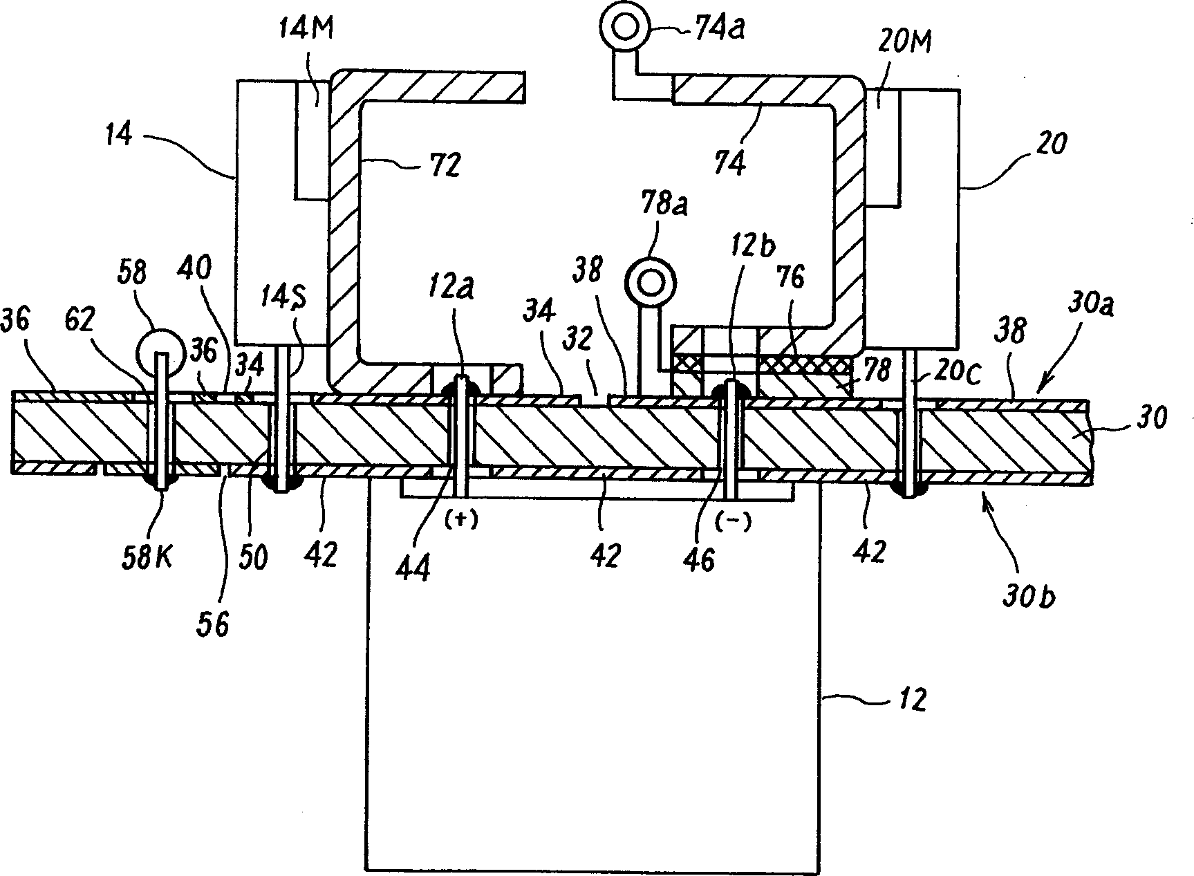
Figure 1 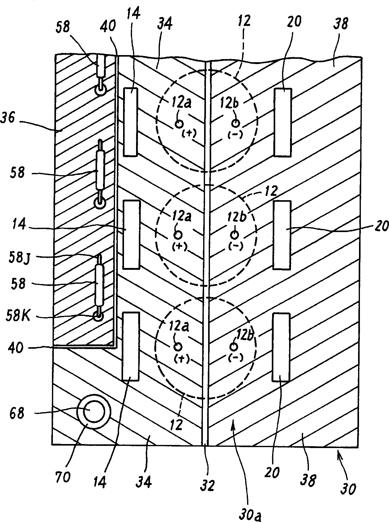
Figure 2 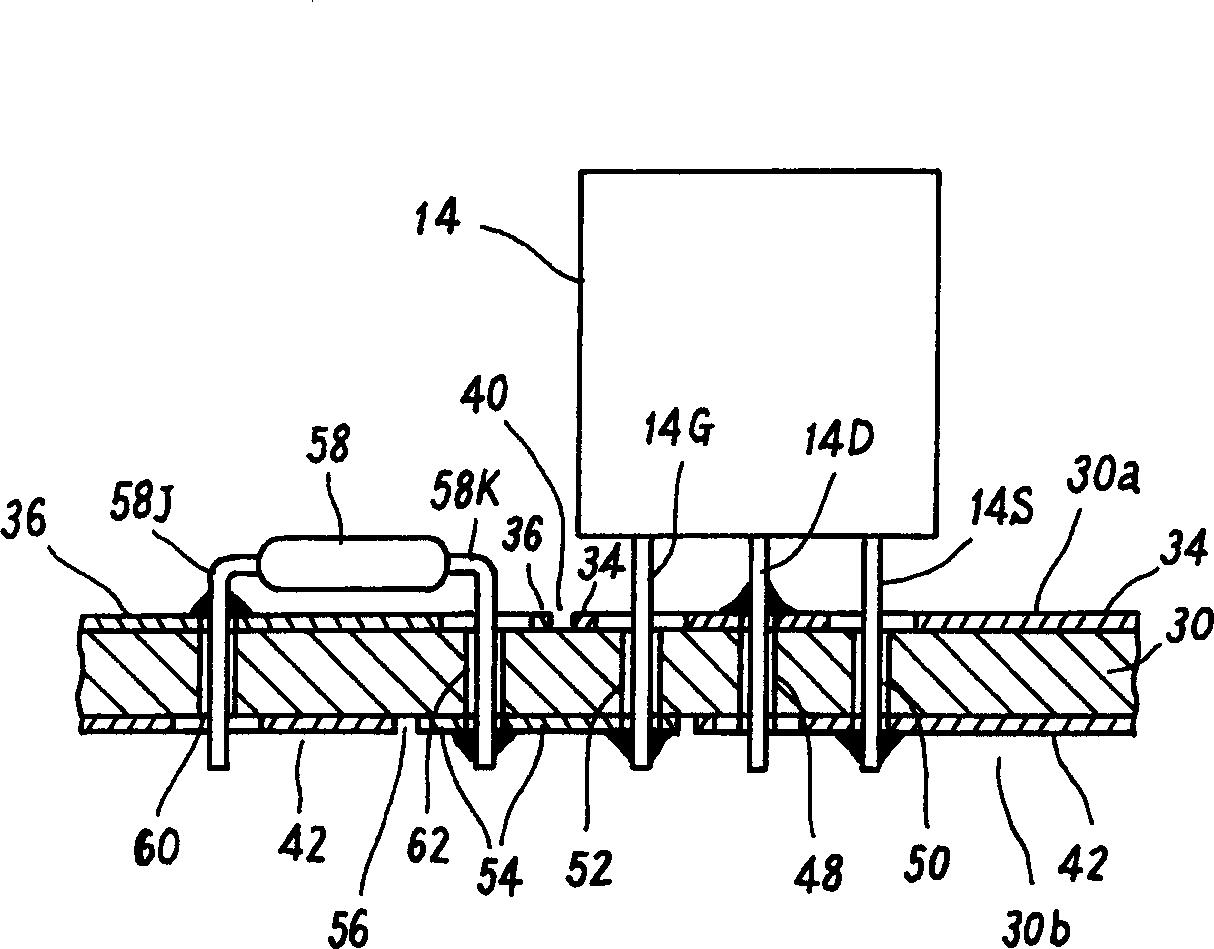
Figure 3
Abstract
Description
technical field
[0001] The present invention relates to a resistance welding device, and more particularly to a resistance welding device in which electric power as welding energy is stored in a capacitor and then supplied to a welded part through a switching element. Background technique
[0002] Image 6 Shows the basic circuit configuration of the main parts of this resistance welding device. The charging circuit 10 includes, for example, a single-phase full-wave rectification circuit composed of a plurality of bridge-connected diodes. The single-phase AC power supply voltage Ea of commercial frequency is input from the AC power line through an insulating transformer (not shown), and the input AC power supply voltage Ea is full-wave Rectification, output DC voltage. The capacitor 12 is charged at a predetermined voltage value Ec by the output voltage of the charging circuit 10 .
[0003] The positive side terminal of the capacitor 12 is electri...
Examples
Embodiment Construction
[0022] Refer below Figure 1 to Figure 5 , illustrating an ideal embodiment of the present invention.
[0023] Figure 1 to Figure 5 It shows the assembly structure of the main part of the resistance welding apparatus of one embodiment of the present invention. The resistance welding device of this embodiment also has Image 6 The circuit structure, such as figure 1 Combinations shown include Image 6 The capacitor 12, the switching transistor 14 and the freewheeling diode 20 of the circuit.
[0024] In this combination, for example, a substrate 30 made of an insulating material such as glass epoxy resin is used as a main body, and one side of the substrate 30 ( figure 1 The lower side of the) install the capacitor 12, on the opposite side ( figure 1 The upper side) of the switch transistor 14 and the freewheeling diode 20 are installed.
[0025] Conductive film conductors made of, for example, copper foil are fixedly formed on both surfaces of the substrate 30 by elec...