
Hydraulic tensioner
A tensioning device, hydraulic technology, applied in the direction of transmission, belt/chain/gear, mechanical equipment, etc., can solve the problem that the tensioning device and the tensioning wheel cannot guarantee the positioning state, the noise of the tensioning device, etc., to avoid unfavorable , to avoid the effect of empty stroke
Patent Information
- Authority / Receiving Office
- CN · China
- Current Assignee / Owner
- Publication Date
- 2005-08-17
- Estimated Expiration
- Not applicable · inactive patent
Smart Images
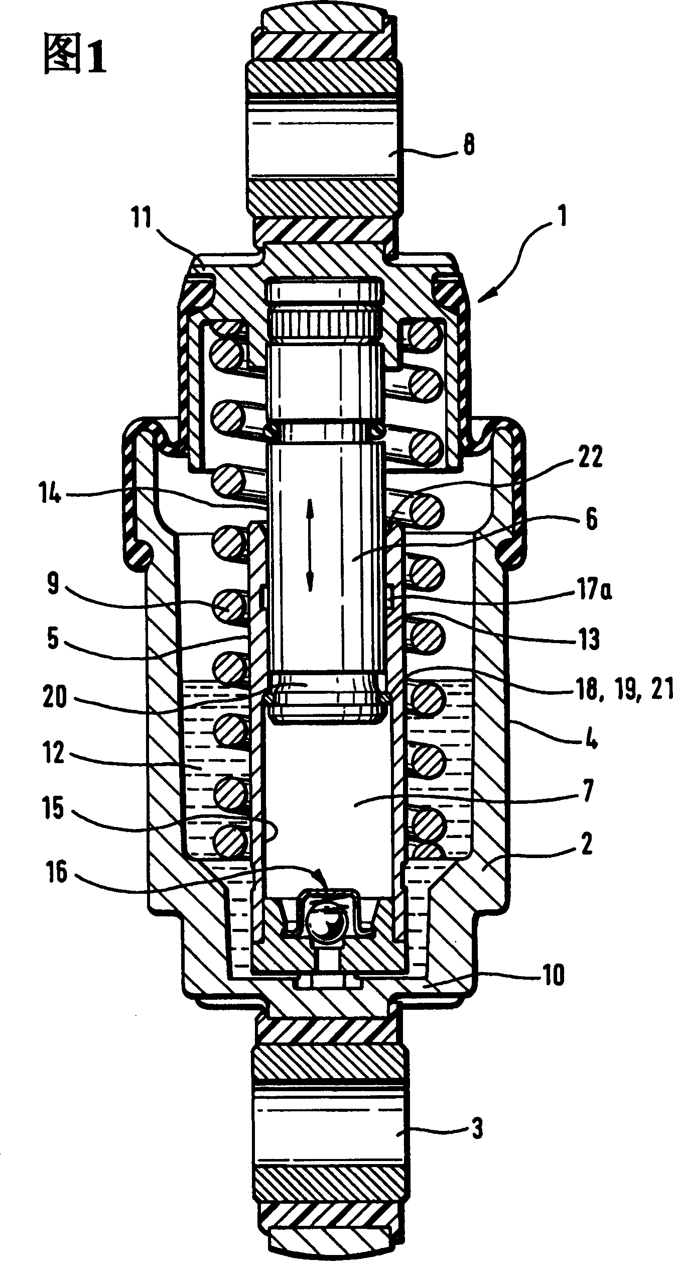
Figure 1 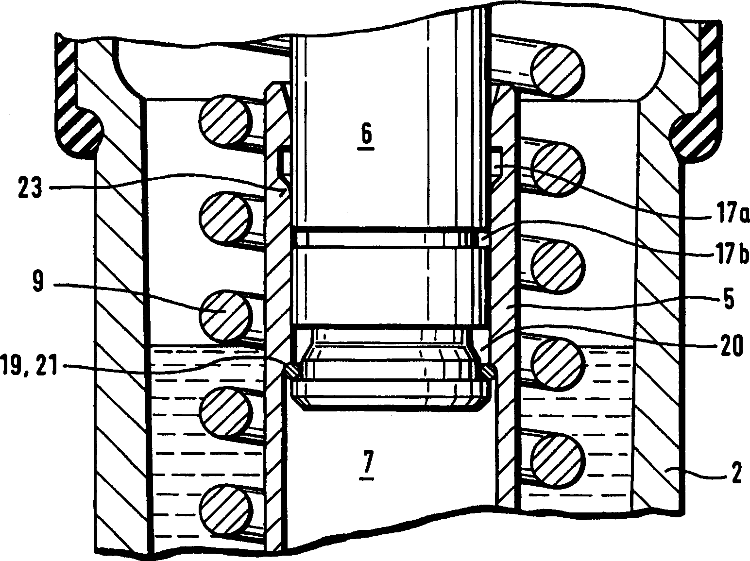
Figure 2 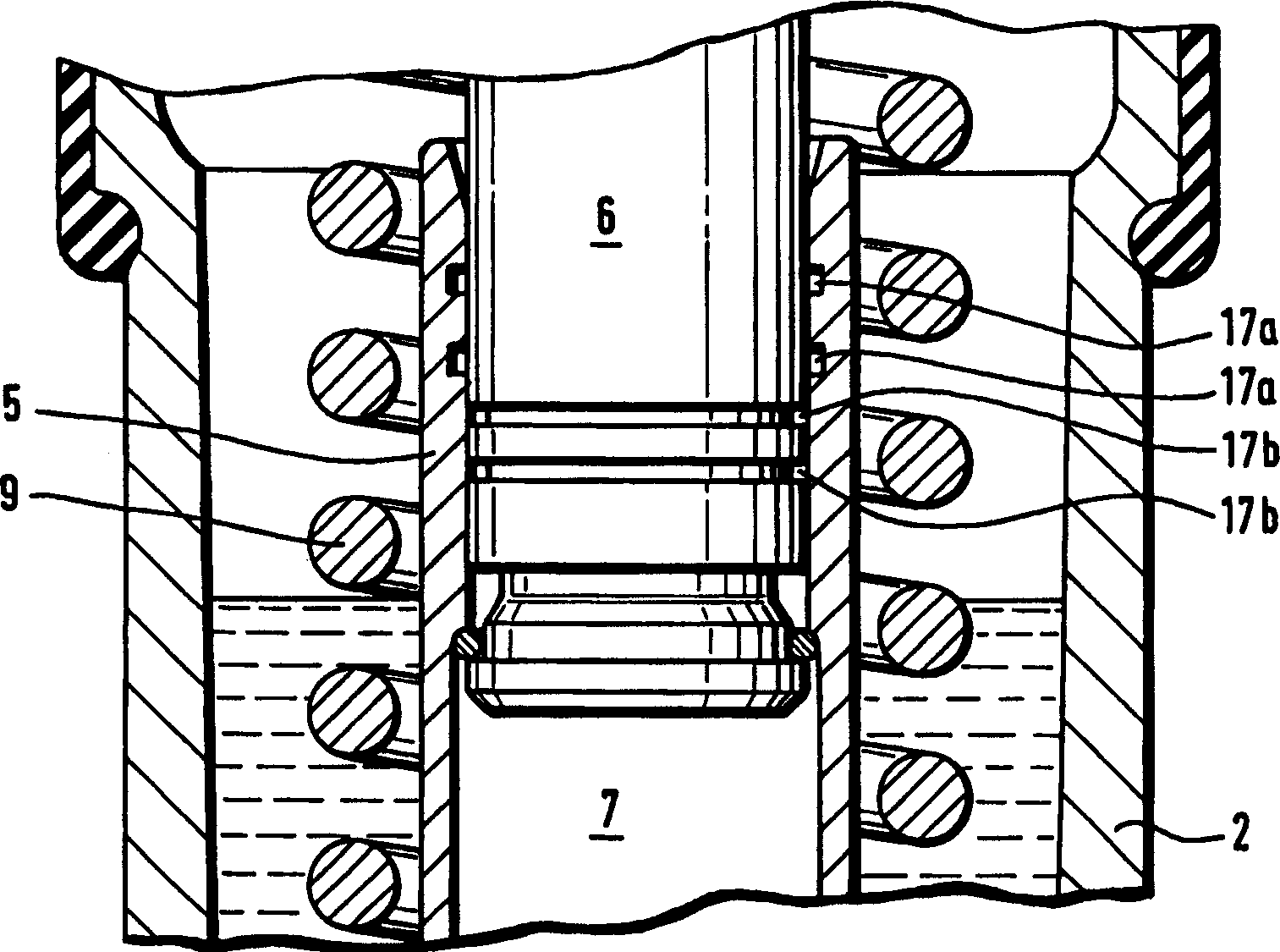
Figure 3
Abstract
Description
technical field
[0001] The invention relates to a hydro-mechanically acting tensioning device for a traction drive. The tensioning device comprises a pot-shaped housing fixed at one end but oscillatingly connected to the housing, and a cylinder concentrically arranged in the housing and radially eccentrically arranged with the outer wall of the housing. A longitudinally displaceable piston is guided in the cylinder, which delimits on one side the cylinder pressure chamber which is filled with hydraulic fluid. At the end remote from the cylinder, the piston can be indirectly connected to a tensioning pulley, which is supported via compression springs on the traction means, in particular on the belt of the traction drive. The pressure chamber of the cylinder is separated by a non-return valve from an annular interior space, which is delimited radially by the outer wall of the cylinder and the inner wall of the housing. In this respect, the annularly formed interior is partiall...
Examples
Embodiment Construction
[0026] FIG. 1 shows a hydromechanically acting tensioning device 1 comprising a rotationally symmetrical pot-shaped housing 2 which is fixed but pivotable by means of fastening lugs 3 to, for example, an internal combustion engine not shown in FIG. 1 . Radially spaced from the outer wall 4, a cylinder 5 in which a longitudinally displaceable guiding piston 6 is housed concentrically within the housing. The piston 6 of the pressure chamber 7 in the end-side delimiting cylinder 5 has, on the end remote from the pressure chamber 7, a fastening lug 8 which interacts indirectly or directly with a tensioning pulley which pretensions the traction drive Traction devices, especially belts. The reasonable power supply of the tensioning wheel is completed by means of the helical compression spring 9. The helical compression spring 9 is supported on the bottom 10 of the housing 2 by the first spring end, and is supported by the second spring end on the fixed lifting lug 8 or on the opposi...