
Rotary wing helicopter
A helicopter and rotor technology, applied in the field of rotor helicopters, can solve problems such as waste of engine power, low lift efficiency, torsional vibration and operation response lag, and achieve the effects of increasing payload, increasing safety and reliability, and reducing weight
Patent Information
- Authority / Receiving Office
- CN · China
- Current Assignee / Owner
- Publication Date
- 2006-10-18
- Estimated Expiration
- Not applicable · inactive patent
Smart Images
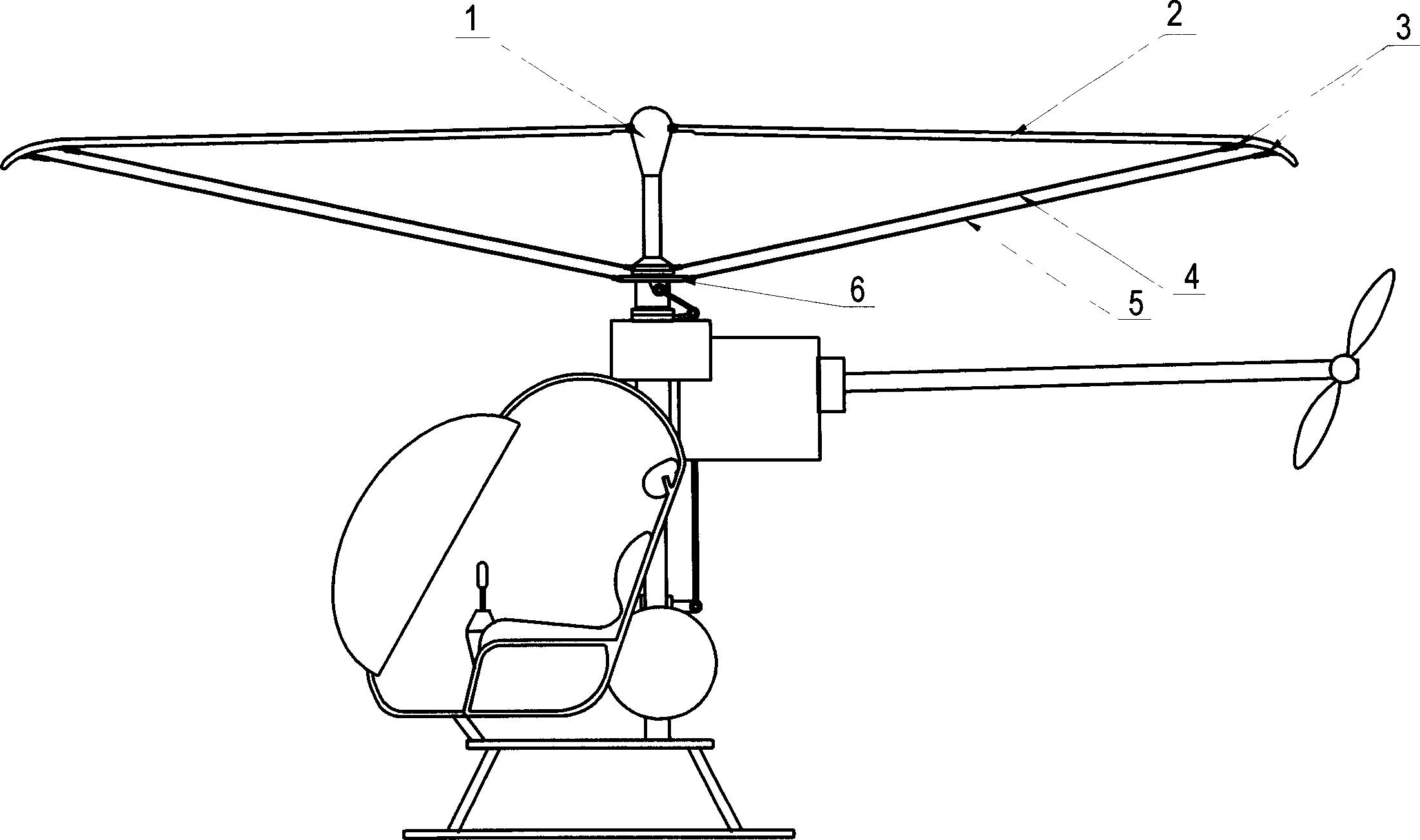
Figure 1 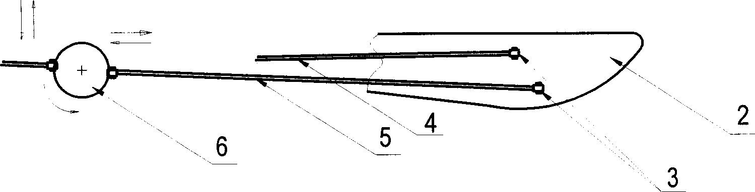
Figure 2
Abstract
Description
Technical field
[0001] The invention relates to a rotor helicopter, in particular to a helicopter with an umbrella surface rotor track.
Background technique
[0002] At present, the rotors of helicopters are all cantilever beam structures, and their wingspans are all designed to be quite long in order to obtain sufficient lift. The severe moment load condition on the normal plane makes the rotor root, flapping hinge and rotating propeller hub necessarily designed to be strong and heavy, so that the effective load is reduced and the manufacturing cost is increased.
[0003] The lift effect makes the rotor of the cantilever beam structure upturned, and its rotation track is an inverted umbrella surface, so that the efficiency of generating lift is low, and a large part of the power of the engine is wasted. The direction control mechanism of the existing helicopter acts on the root of the inner end of the rotor, and the most effective part of the aerodynamic force is the o...
Examples
Embodiment Construction
[0016] see figure 1 and figure 2 , is a preferred embodiment of the present invention, the helicopter of the canopy rotor track of the present invention has rotor 2 and rotating propeller hub 1, and the root of rotor 2 is hinged on the upper end of propeller hub 1, and at the outer end of rotor 2 and paddle At least one connecting piece 4 is connected between the hubs 1, the connecting piece 4 can be a tension cable or a connecting rod, and its two ends are respectively hinged on the outer end of the rotor 2 and the lower end of the propeller hub 1, during work, the rotor 2 and connecting piece 4 rotate together with the propeller hub 1.
[0017] A control ring 6 is also arranged below the above-mentioned propeller hub 1. The control ring 6 is a translational control ring, which rotates synchronously with the propeller hub 1 and can translate on the vertical plane of the rotating shaft at the same time, so that the rotor 2 can move in the whole The lift force on each sector...