
Control circuit for power converter
A technology of power converter and control circuit, which is applied in the direction of output power conversion device, conversion of DC power input to DC power output, control/regulation system, etc., and can solve problems such as low-pass filter characteristics and waveform distortion
Patent Information
- Authority / Receiving Office
- CN · China
- Current Assignee / Owner
- Publication Date
- 2006-10-25
Smart Images
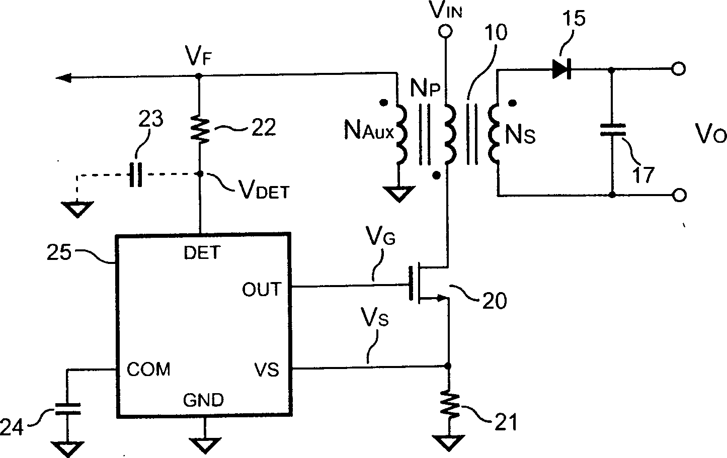
Figure 1 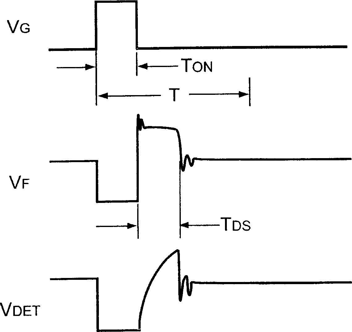
Figure 2 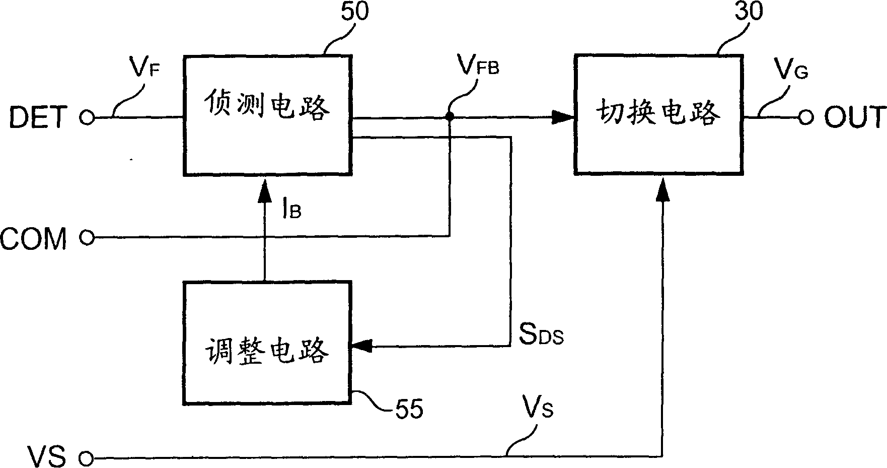
Figure 3
Abstract
Description
Technical field:
[0001] The invention relates to a power converter, in particular to a control circuit of the power converter. Background technique:
[0002] According to, power converters are widely used to provide regulated output power today. In consideration of safety, the primary side and the secondary side of the power converter must be isolated, so the power converter is usually provided with a transformer for providing isolation and transferring energy. see figure 1 , is the circuit diagram of a conventional power converter. As shown in the figure, a conventional power converter is provided with a transformer 10, which includes a primary winding N P , primary and secondary side winding N S with an auxiliary winding N AUX , primary side winding N P respectively coupled to an input voltage V IN with a switch 20 . When the switch 20 is turned on, the primary side of the transformer 10 will store energy. Once the switch 20 is turned off, the transformer 10 will r...
Examples
Embodiment Construction
[0062] In order to enable the examiner to have a further understanding and understanding of the structural features and achieved effects of the present invention, I would like to provide a better embodiment diagram and a detailed description,
[0063] The instructions are as follows:
[0064] The control circuit of the power converter of the present invention includes a switch and a controller. The controller generates a control signal to control the coupled switch to switch the transformer of the power converter. see image 3 , is a block diagram of a controller of a preferred embodiment of the present invention. As shown in the figure, the controller of the present invention includes a switch circuit 30 , a detection circuit 50 and an adjustment circuit 55 . The detection circuit 50 is coupled to the transformer 10 via the voltage detection terminal DET to detect the flyback voltage V of the transformer 10 F , to depend on the flyback voltage V F generate a first signal ...