
Chassis link for a motor vehicle
a technology for chassis links and motor vehicles, applied in mechanical devices, transportation and packaging, other domestic objects, etc., can solve problems such as compressive loading and reduced stiffness, and achieve the effects of/or buckling strength, increasing adhesion surface, and increasing bending stiffness and/or torsional stiffness
Patent Information
- Authority / Receiving Office
- US · United States
- Patent Type
- Patents(United States)
- Current Assignee / Owner
- Publication Date
- 2021-11-16
Smart Images
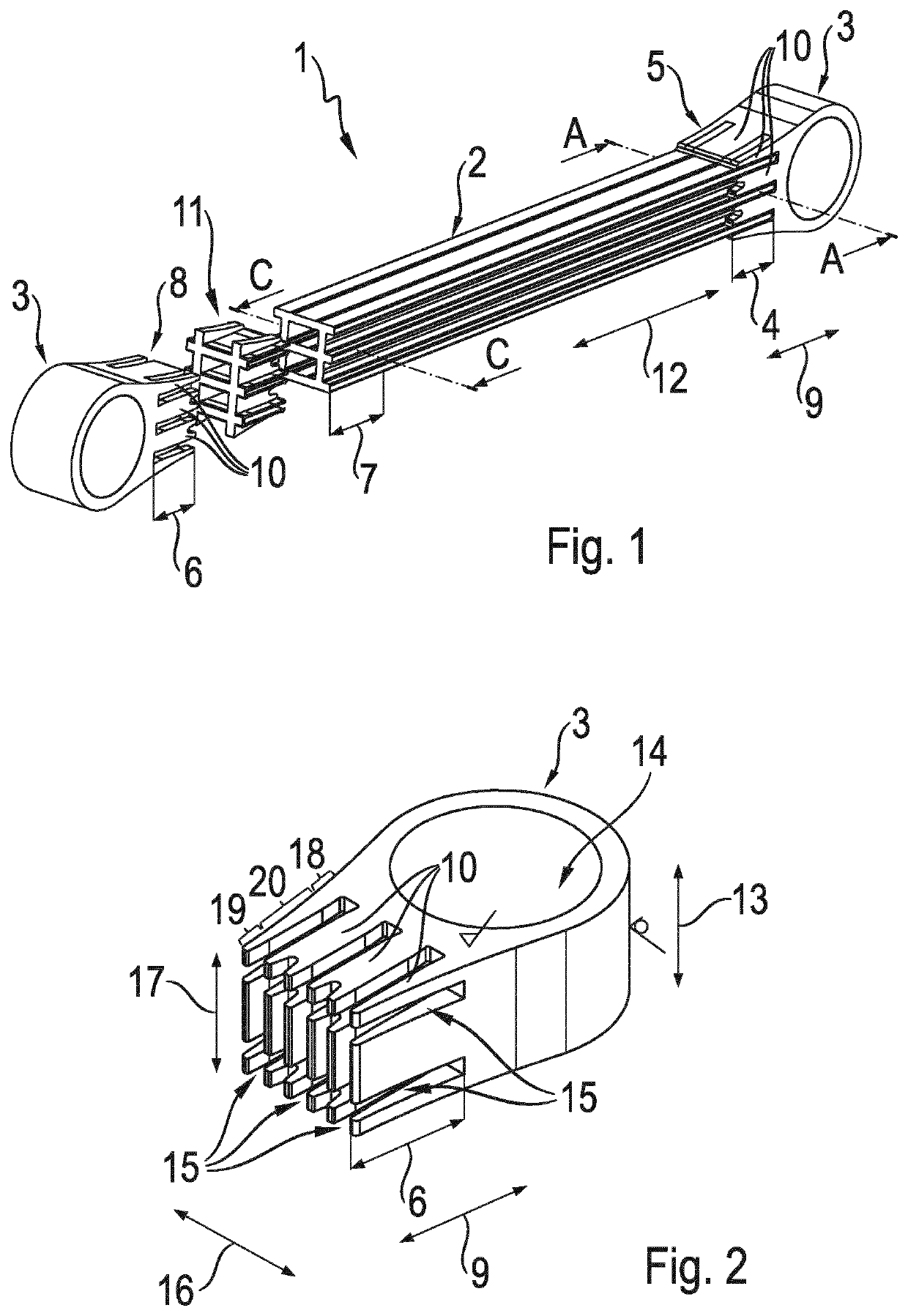
Figure 1 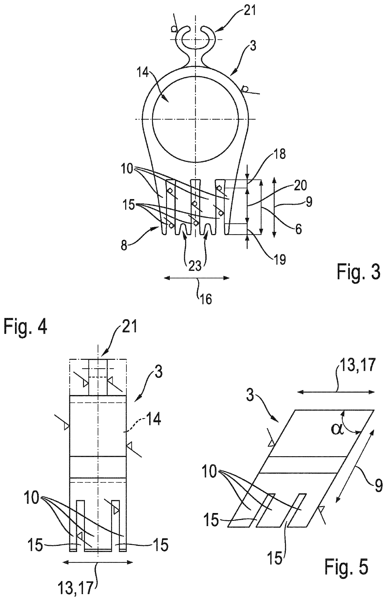
Figure 2 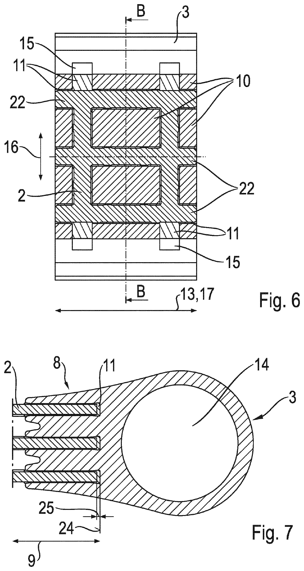
Figure 3
Abstract
Description
CROSS REFERENCE TO RELATED APPLICATIONS
[0001] This is a U.S. national stage of Application No. PCT / EP2019 / 060844 filed Apr. 29, 2019. Priority is claimed on German Application No. DE 10 2018 208 282.0 filed May 25, 2018 the content of which is incorporated herein by reference.BACKGROUND OF THE INVENTION1. Field of the Invention
[0002] The invention is directed to a component part for a motor vehicle, having a hollow profile portion made of a fiber-reinforced plastic and a load introduction element made of a metal material.2. Description of Related Art
[0003] Component parts for motor vehicles having a hollow profile portion made of a fiber-reinforced plastic and a load introduction element made of a metal material are known from the prior art. A strut-shaped component part of fiber-reinforced plastic which is formed as a tubular hollow profile is disclosed in DE 10 2010 053 843 A1. The strut-shaped component part is connected via a nondetachable plug-in connection to a load introduction ...
Examples
Embodiment Construction
[0049]FIG. 1 shows a chassis link 1, also referred to as axle strut, formed as a two-point link. The chassis link 1 has a pultruded hollow profile portion 2 of fiber-reinforced plastic and two load introduction elements 3 of aluminum. The hollow profile portion 2 and the load introduction elements 3 are connected to one another in common connection portions 4 via nondetachable glued plug-in connections 5. With respect to the two plug-in connections 5, an end portion 6 of the load introduction element 3 and an end portion 7 of the hollow profile portion 2 mutually engage one inside the other substantially in positive engagement. The end portion 6 of the load introduction element 3 has a spline 8 with twelve teeth 10 extending in longitudinal direction 9 of the common connection portion 4 so that the stiffness of the end portion 6 of the load introduction element 3 in longitudinal direction 9 of the common connection portion 4 is reduced. In the common connection portion 4, the end po...