
Pipe joint
a technology for pipes and joints, applied in the direction of hose connections, adjustable joints, sleeve/socket joints, etc., can solve the problems of difficult quality control and achieve the effect of simple work, easy maintenance and keeping a certain level of quality
Patent Information
- Authority / Receiving Office
- US · United States
- Patent Type
- Applications(United States)
- Current Assignee / Owner
- Publication Date
- 2005-01-13
Smart Images
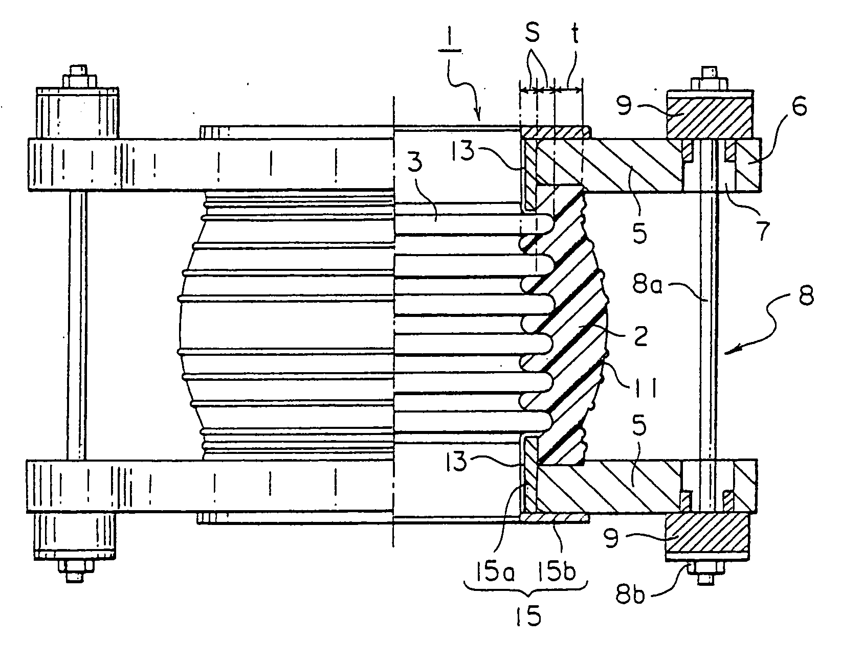
Figure 1 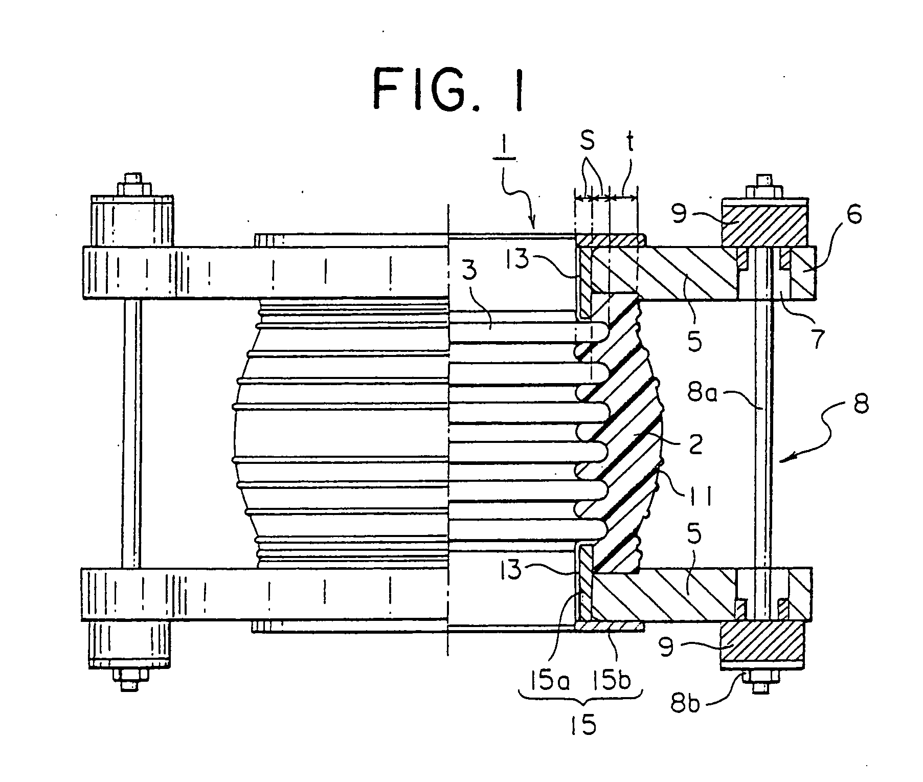
Figure 2 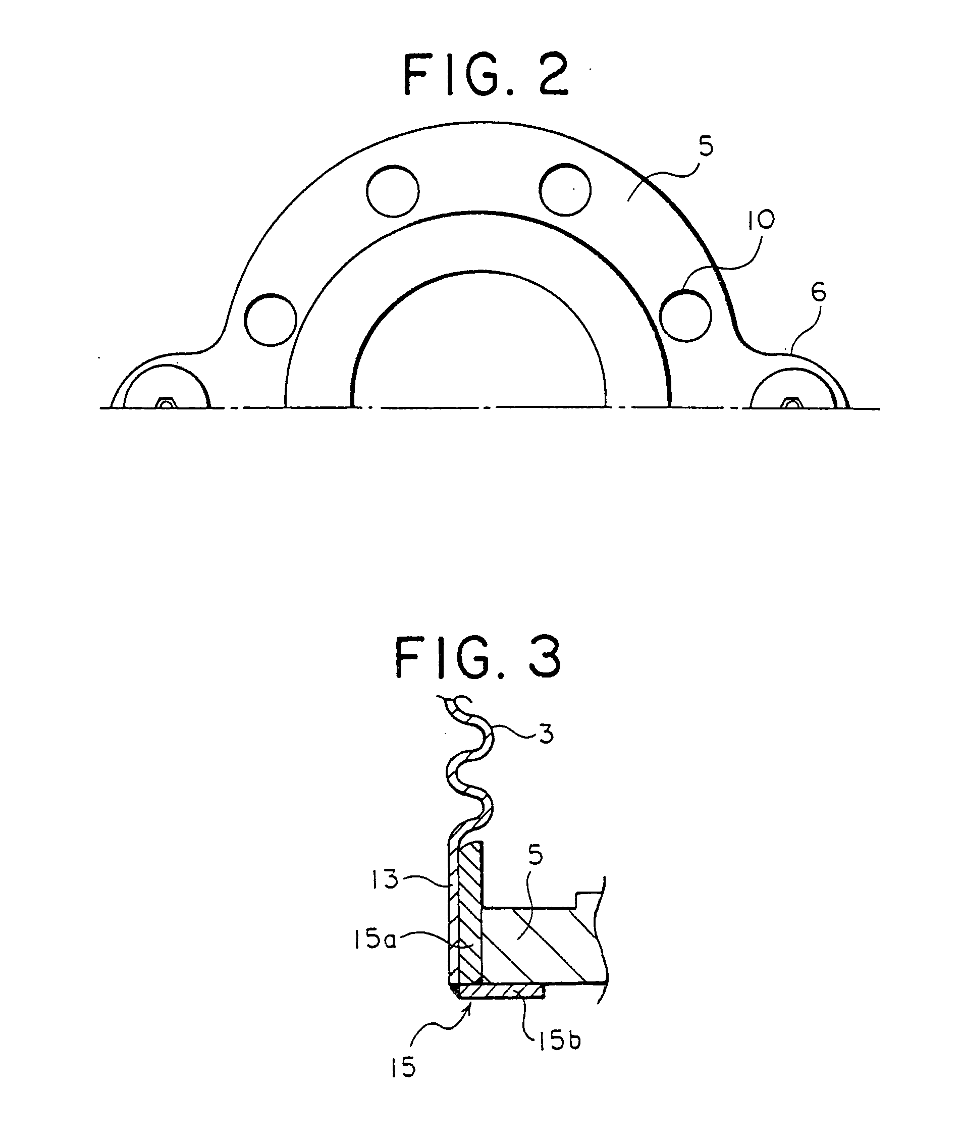
Figure 3
Abstract
Description
FIELD OF THE INVENTION
[0001] The present invention relates to a pipe joint connecting piping used for fluid circulation. BACKGROUND OF THE INVENTION
[0002] A pipe joint 51 according to the conventional technology comprises, as shown in FIG. 7, a hollow cylindrical joint body 52 made of elastic material such as heat-resistant rubber with a prescribed length, and a circular flange 55 for connecting piping attached onto the both ends of the joint body 52. The flange 55 is metallic and is fitted into and attached to the both ends of the joint body 52 in a way that the both ends of the joint body 52 are elastically deformed inwardly to make their diameter smaller. In order to maintain the capacity of the joint body 52 to resist pressure, a reinforcement member 60 such as synthetic fiber is embedded at a prescribed position in the joint body 52. The reference numeral 58 is a stopper member for maintaining capacity to resist pressure attached to the two flanges 55 connecting one flange to...
Examples
Embodiment Construction
[0013] One embodiment of the present invention is described with reference to the drawings.
[0014] The reference numeral 1 is a pipe joint comprising a hollow cylindrical joint body 2 made of elastic material such as heat-resistant rubber with a prescribed length. On the side of the inner circumference of the joint body 2 is provided a bellows metal pipe 3 closely contacted with the joint body 2. Namely, the metal pipe 3 is formed with a plurality of bellows in the direction of the pipe's axis at regular intervals in the circular form, so that the inner circumference section of the joint body 2 is filled up to and closely contacted with the trough of the outer circumferential surface. On the both sides of the metal pipe 3 and the joint body 2 (upward and downward in FIG. 1) is each attached a metal circular flange 5 for connecting piping. On the flange 5 is formed an expanded section 6 at a position opposing to each other, and into the expanded section is bored a piercing hole 7, an...