
Self-adjusting snow plow
a self-adjusting, snow plow technology, applied in snow cleaning, way cleaning, construction, etc., can solve the problems of individuals purchasing and using such vehicles, affecting the use of pedestrian and vehicular travel surfaces, and removing snow from open ground, etc., to achieve easy drawing of the plow blades and simple installation
Patent Information
- Authority / Receiving Office
- US · United States
- Current Assignee / Owner
- Publication Date
- 2005-03-31
- Estimated Expiration
- Not applicable · inactive patent
Smart Images
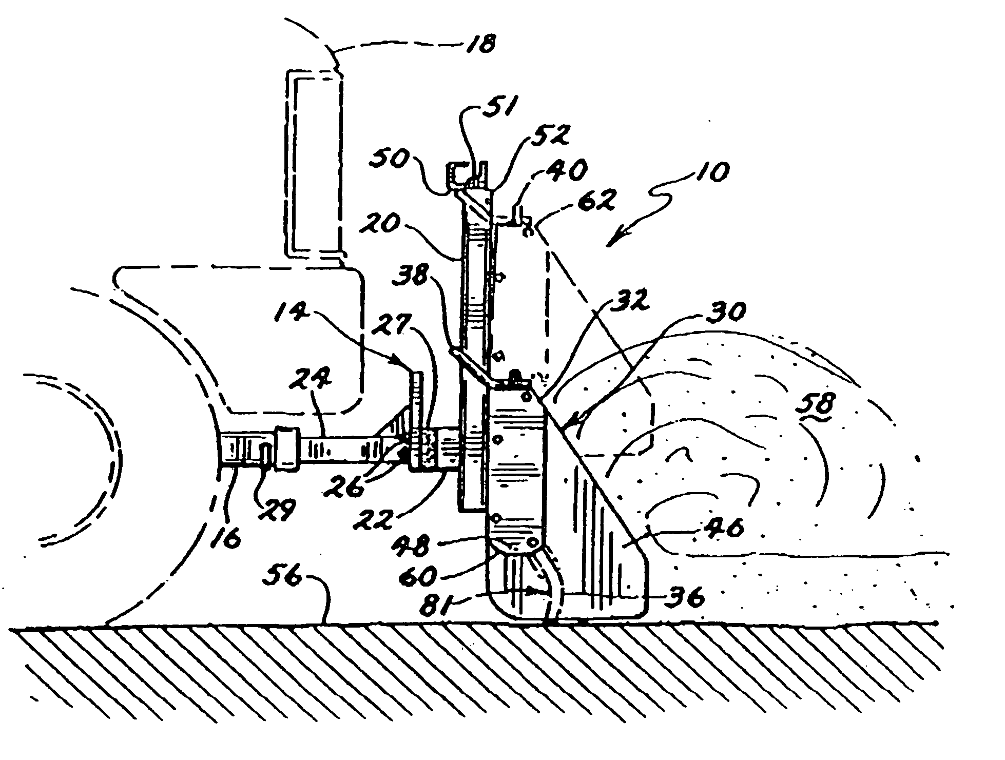
Figure 1 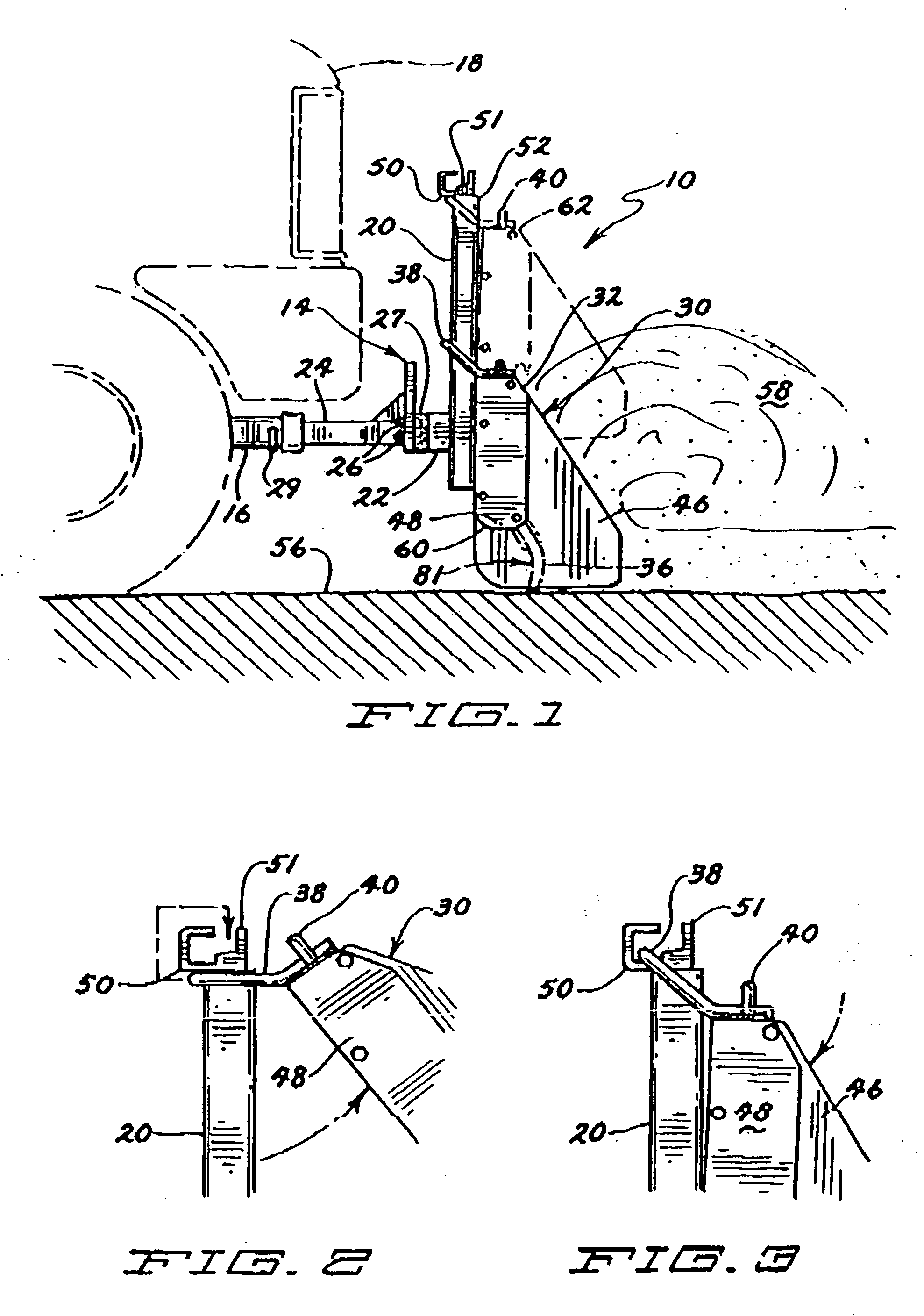
Figure 2 
Figure 3
Abstract
Description
RELATED APPLICATIONS
[0001] The present application is related to and claims priority to U.S. patent application Ser. No. 10 / 841,740, filed May 7, 2004 and U.S. patent application Ser. No. 10 / 404,164, filed Mar. 31, 2003, (issuing Nov. 16, 2004, as U.S. Pat. No. 6,817,118) both entitled Self-Adjusting Snow Plow, both of which claim priority to PCT application No. PCT / US01 / 47125 for SELF-ADJUSTING SNOW PLOW, filed Nov. 12, 2001, and each of which are hereby incorporated by reference.FIELD OF THE INVENTION
[0002] The present invention relates to adjustable snow plows for attachment to personal utility vehicles such as pickup trucks and sport utility vehicles. BACKGROUND OF THE INVENTION
[0003] Moving snow off of open ground, streets, sidewalks and parking lots is an age-old problem in less temperate climates where significant snowfall is anticipated during colder periods of the year. For instance, in many parts of Canada and in many northern states in the United States, significant sn...
Examples
Embodiment Construction
[0042] Referring now to the drawings, and more particularly FIGS. 1-3, a preferred self-adjusting snow plow 10 of the present invention is shown. The preferred snow plow 10 includes a mounting apparatus 14 and a plow blade 30. Referring now also to FIGS. 7 and 8, the preferred mounting apparatus 14 includes a hitch receiver 16 which is secured to a vehicle 18 (partially shown in phantom in FIG. 1). The mounting apparatus 14 also includes two mounting uprights 20 that are interconnected by an interconnecting member 22. In this embodiment, a hitch tongue 24 is secured to the interconnecting member 22 by a series of bolts 25 secured by nuts 26. The bolts 25 secure the hitch tongue 24 to the interconnecting member 22 with a resilient rubber connecting member 27 interspersed between the interconnecting member 22 and a flat connecting plate 28 of the hitch tongue 24. A securing pin 29 secures the hitch tongue in the hitch receiver 16. The resilient rubber connecting member 27 allows the e...