
UHF broadband antenna
a broadband antenna and broadband technology, applied in the direction of antennas, antenna feed intermediates, electrical devices, etc., can solve the problems of bulky element type dipole antennas, and large number of structural components of this antenna, so as to prevent deterioration of directivity, simple and compact structure, and high performance
Patent Information
- Authority / Receiving Office
- US · United States
- Patent Type
- Applications(United States)
- Current Assignee / Owner
- Publication Date
- 2005-07-28
- Estimated Expiration
- Not applicable · inactive patent
Smart Images
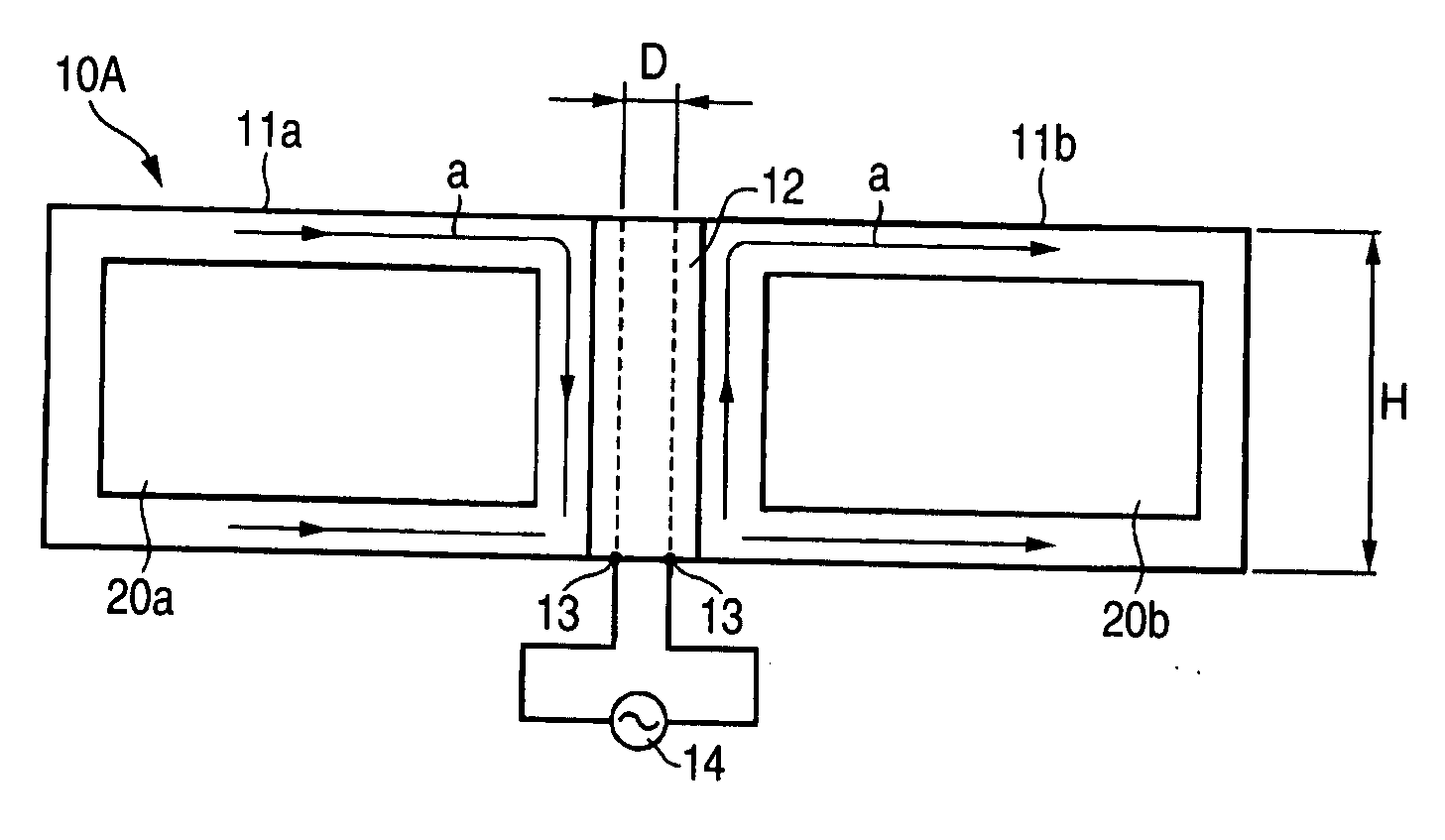
Figure 1 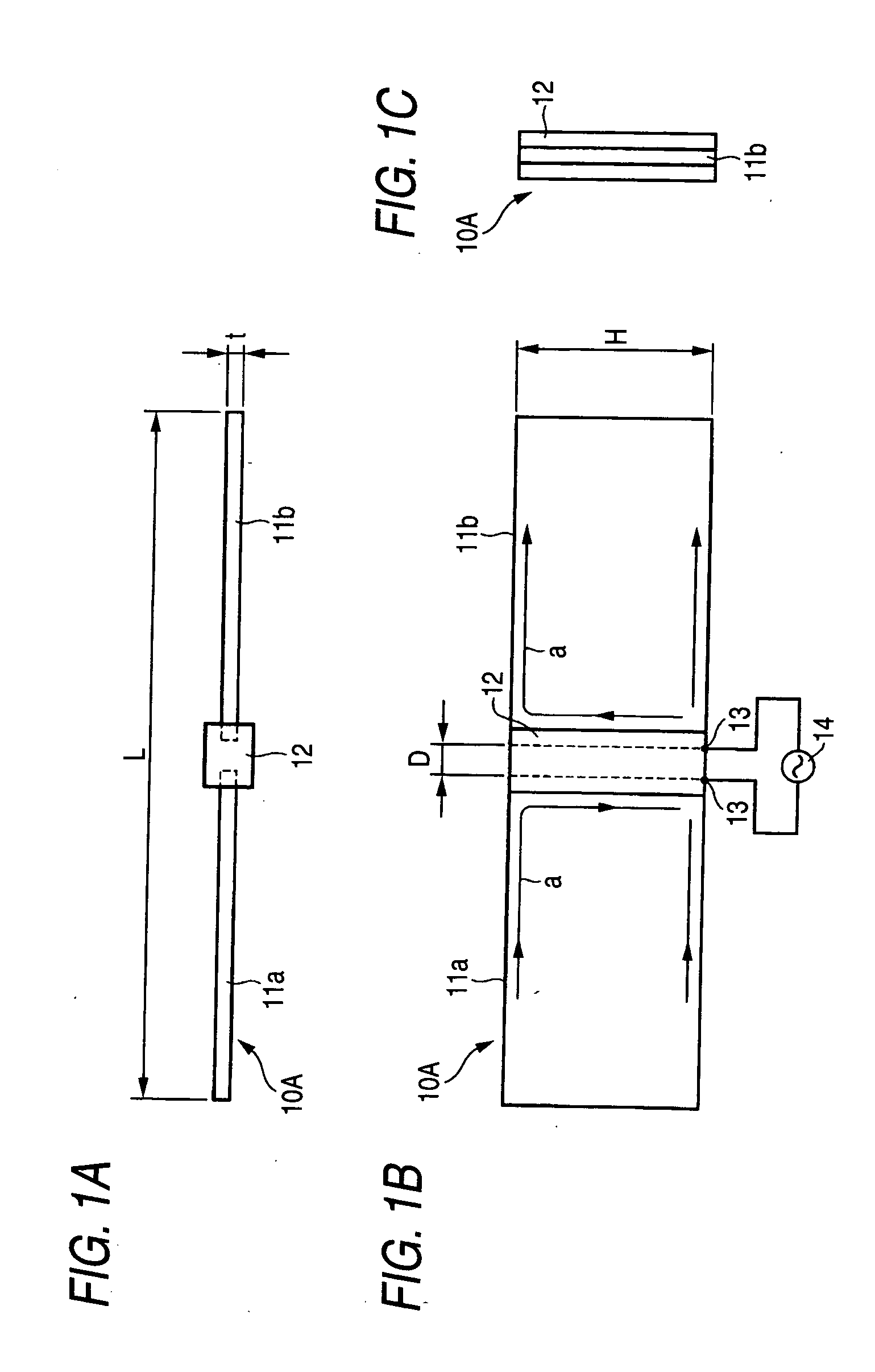
Figure 2 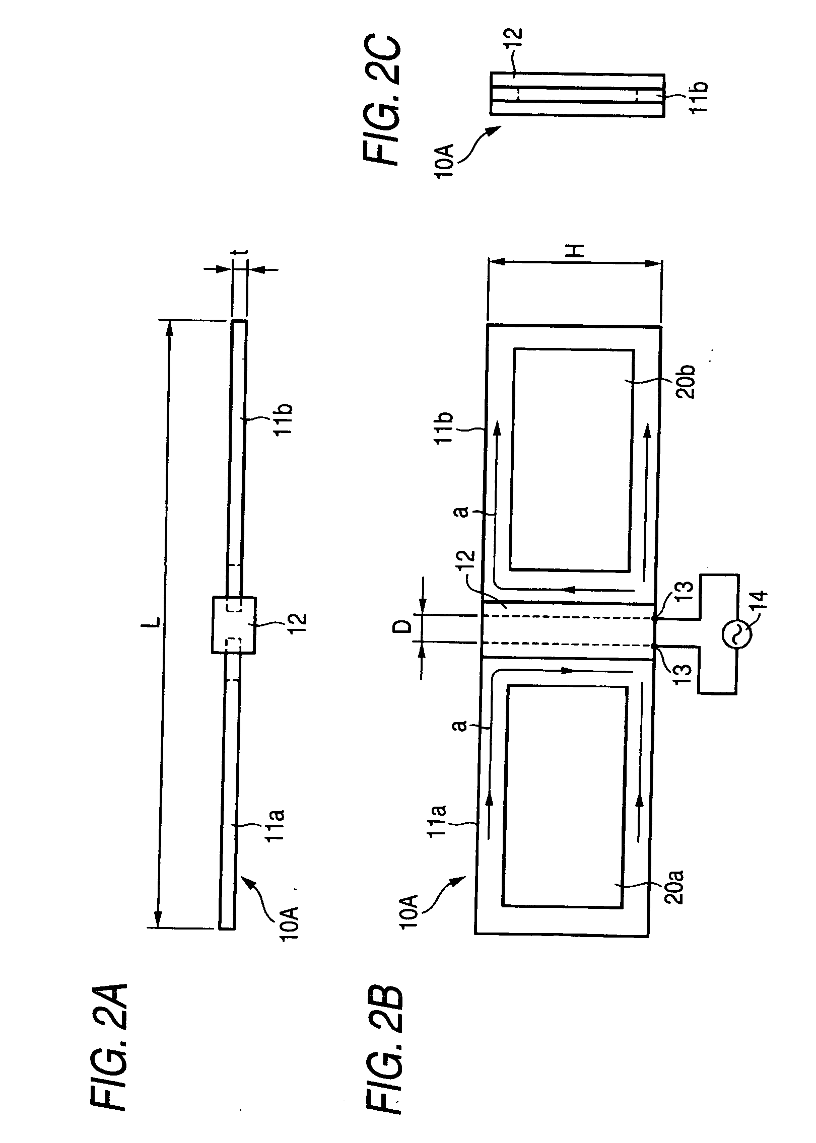
Figure 3
Abstract
Description
BACKGROUND OF THE INVENTION
[0001] The present invention is related to an UHF broadband antenna which is used in, for example, UHF band ground wave broadcasting and communications.
[0002] ISTB-T (Terrestrial Integrated Services Digital Broadcasting) programs have already been commenced since 2003 in limited regions of Japan, and are scheduled to be started in other regions of Japan until 2006.
[0003] As to the above-described Terrestrial Integrated Services Digital Broadcasting system, electromagnetic waves in UHF band are used, and a frequency range thereof is scheduled to be enlarged to 470 through 770 MHz.
[0004] Conventionally, two-element type dipole antennas are known as antennas which receive electromagnetic waves in the UHF band (refer to, for instance, Japanese Patent Publication No. 2003-273637A).
[0005] One conventional two-element type dipole antenna is constructed as shown in FIGS. 27A to 27C. In this type of antenna, first dipole elements 1a, 1b, and second dipole elem...
Examples
first embodiment
[0086]FIGS. 1A to 1C show a UHF broadband antenna 10A according to the present invention. In this embodiment, plate-shaped dipole elements 11a, 11b each of which is a metal plate having a shape of, for example, substantially rectangle. The plate-shaped dipole elements 11a, 11b are arranged, while a predetermined interval “D” therebetween is maintained. A center portion of the antenna 10A, edge portions of these dipole elements 11a, 11b located opposite to each other are held by a retainer 12 made of an insulative material. The above-described dipole elements 11a, 11b have been designed as follows. That is, for instance, an entire length “L” of these dipole elements 11a, 11b has been set to approximately 0.35 λa; a height “H” has been set to be longer than, or equal to approximately 0.06 λa; a thickness “t” has been set to be smaller than, or equal to approximately 0.002 λa; and also, the interval “D” has been set to 0.006 to 0.025 λa. It should be understood that the above-described...
second embodiment
[0098]FIGS. 8A to 8C show a UHF broadband antenna 10B according to the present invention.
[0099] In this embodiment, a folded element 15 which has been manufactured by a metal plate is provided on rear face sides of dipole elements 11a, 11b which are held by a retainer 12. In this case, the folded element 15 is provided in such a manner that this folded element 15 is located along, for example, a substantially center on the rear face sides of the dipole elements 11a, 11b. It should also be noted that the same reference numerals shown in the first embodiment will be employed as those for denoting the same structural elements of the second embodiment, and detailed explanations thereof are omitted.
[0100] A thickness of the above-described folded element 15 is set to be the same to 0.0015 / a as that of the dipole elements 11a, 11b; and a height “Ha” is set to be higher than, or equal to 0.0015 λa, namely lower than the height “H” of the dipole elements 11a, 11b. Also, a folded width “Wa”...
third embodiment
[0108]FIGS. 13A to 13C show a UHF broadband antenna according to the present invention.
[0109] In this embodiment, an antenna 10C having a reflecting plate is equipped with the UHF broadband antenna 10A according to the first embodiment as a driven element. In other words, a reflecting plate 21 is provided behind the antenna 10A of the first embodiment with a predetermined interval, and the retainer 12 of the antenna 10A is supported via a supporting pillar 22 at a center portion of this reflecting plate 21. The above-explained reflecting plate 21 is formed in a shape of, for example, a rectangular shape, and owns a sufficiently large area relative to the antenna 10A.
[0110] With this configuration, a gain thereof along the forward direction can be further increased and high performance thereof can be obtained, as compared in those of the antenna 10A of the first embodiment.
[0111] Also, since the antenna 10A is capable of avoiding that the maximum value direction of the directivity ...