
Stepping motor driver
a technology of stepping motors and drivers, applied in the direction of electric generator control, dynamo-electric converter control, dynamo-electric gear control, etc., can solve the problems of large power consumption, less efficiency, and high so as to reduce power consumption of stepping motors and suppress heat generation of stepping motors
Patent Information
- Authority / Receiving Office
- US · United States
- Patent Type
- Applications(United States)
- Current Assignee / Owner
- Publication Date
- 2005-10-06
- Estimated Expiration
- Not applicable · inactive patent
Smart Images
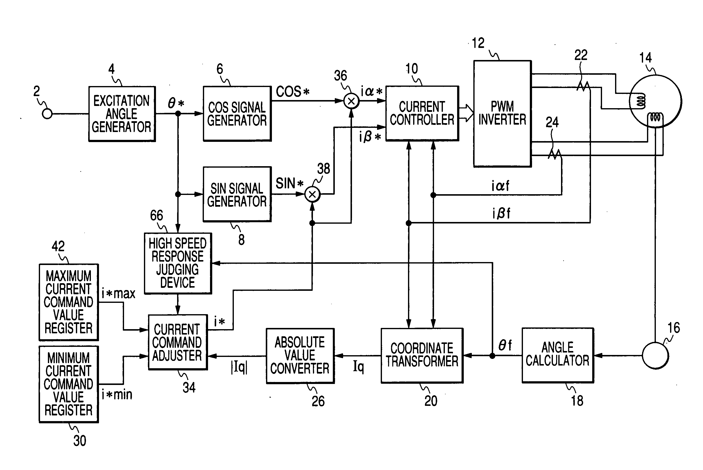
Figure 1 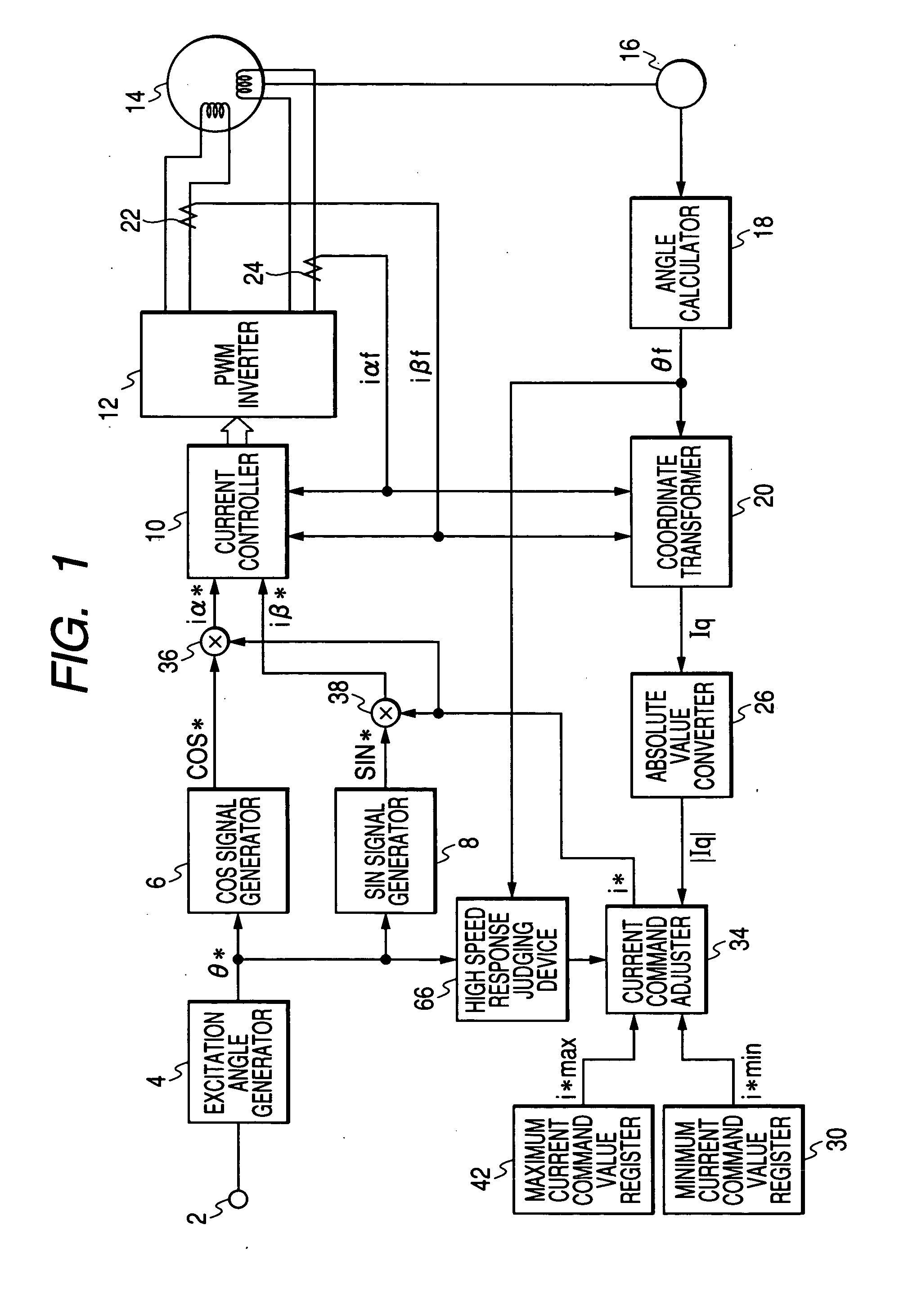
Figure 2 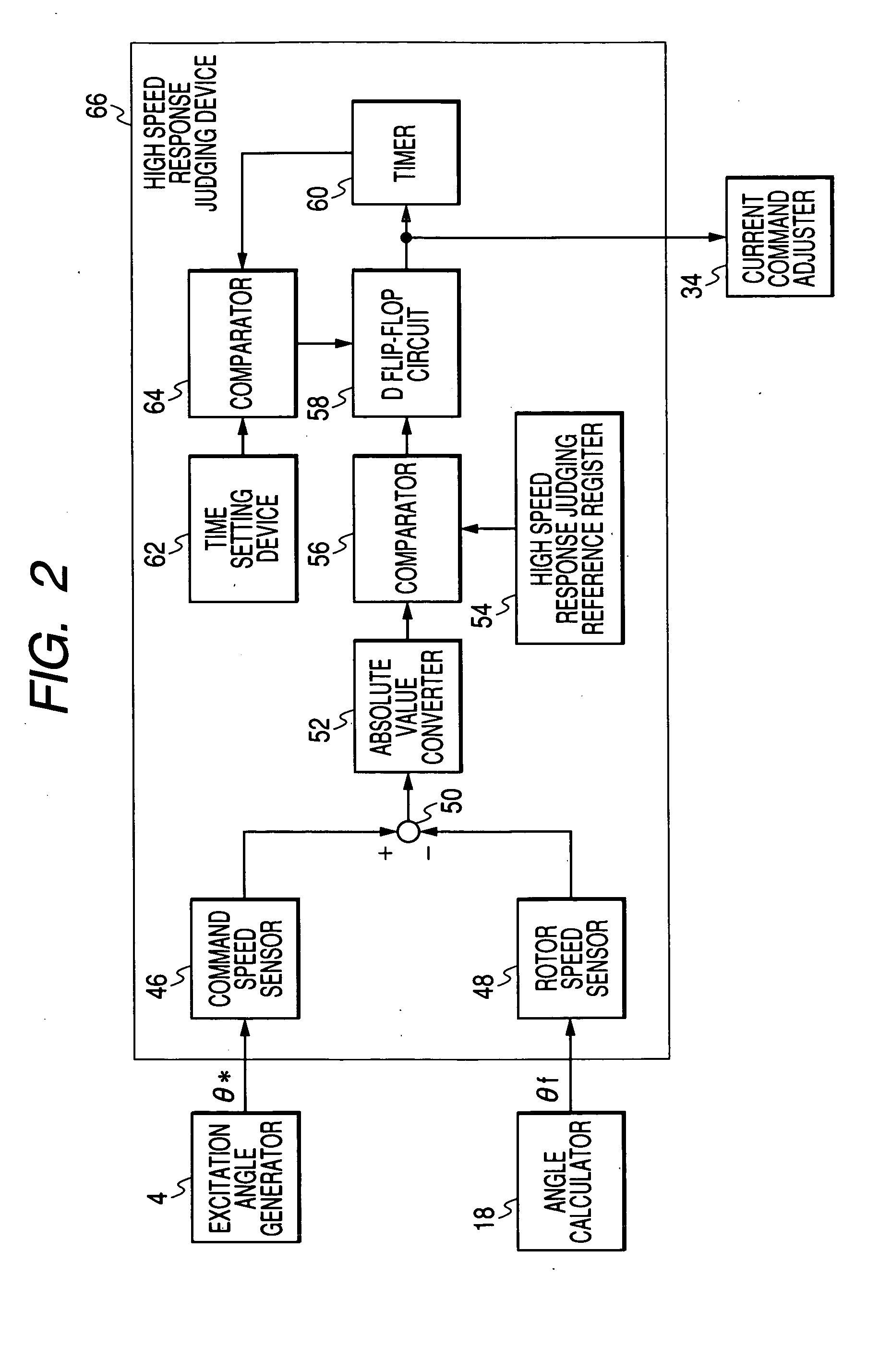
Figure 3
Abstract
Description
BACKGROUND OF THE INVENTION
[0001] 1. Field of the Invention
[0002] The present invention relates to a stepping motor driver which drives a stepping motor for control of the position and speed of driven equipment.
[0003] 2. Description of the Prior Art
[0004] In most conventional stepping motors, a current command is fixed.
[0005] Therefore, there is a problem that a stepping motor consumes much power and is less efficient because a fixed current flows even while it is stopped or running at a low speed.
[0006] As a solution to this problem, the following approach to reduce power consumption has been taken: during motor running, a command for a current which is enough to generate a required torque is selected and upon elapse of a given time after a motor stop, the value of the current command is decreased to the necessary minimum.
[0007] However, even in this case, since the exciting current of the stepping motor is controlled with a fixed current command during motor running, its po...
Examples
first embodiment
[0016] Referring to FIGS. 1 to 3, a stepping motor driver according to the present invention will be discussed hereinafter.
[0017] An excitation angle generator 4 generates an excitation angle θ* from an external command pulse added to an external command pulse input terminal 2. A COS signal generator 6 and a SIN signal generator 8 respectively generate COS signal COS* and SIN signal SIN* using the excitation angle θ*. Multipliers 36 and 38 multiply a current command i* (explained later) by COS signal COS* and SIN signal SIN* and generate alpha-phase current command iα* (i*cos θ*) and beta-phase current command iβ* (i*sin θ*), respectively. A current controller 10 receives phase currents iαf and iβf (explained later) and controls an exciting current (motor winding current) so as to cause it to agree with the alpha-phase current command iα* and beta-phase current command iβ*, respectively. A PWM inverter 12 applies a given voltage to a stepping motor 14 according to output of the curr...
second embodiment
[0027] Referring to FIG. 5, a stepping motor driver according to the present invention will be discussed hereinafter. A current command processor 78 receives the load torque equivalent-current command value and a control signal from the high speed-response judging device 66, and outputs λ3. Namely, when the first control signal is outputted from the high speed-response judging device 66, the current command processor 78 outputs the load torque equivalent-current command value as λ3 and when the second control signal is outputted from the high speed-response judging device 66, the current command processor 78 outputs zero as π3. An adder 80 obtains a difference value ε1 which is a difference between the output λ3 and the maximum current command value i*max. An adder 82 obtains a difference value ε2 which is a difference between the output λ3 and the minimum current command value i*min. A current command processor 84 receives the difference value ε1, and a control signal from the high...