
Hand-operated inflator
a hand-operated, inflator technology, applied in the direction of pump components, positive displacement liquid engines, liquid fuel engine components, etc., can solve the problems of troublesome assembling and disassembly of dual-cylinder inflators, the inability to quickly refuel inflatable objects, and the long time-consuming and labor-intensive task of filling inflatable objects, etc., to achieve convenient use and maintenance
Patent Information
- Authority / Receiving Office
- US · United States
- Current Assignee / Owner
- Publication Date
- 2006-09-07
- Estimated Expiration
- Not applicable · inactive patent
Smart Images
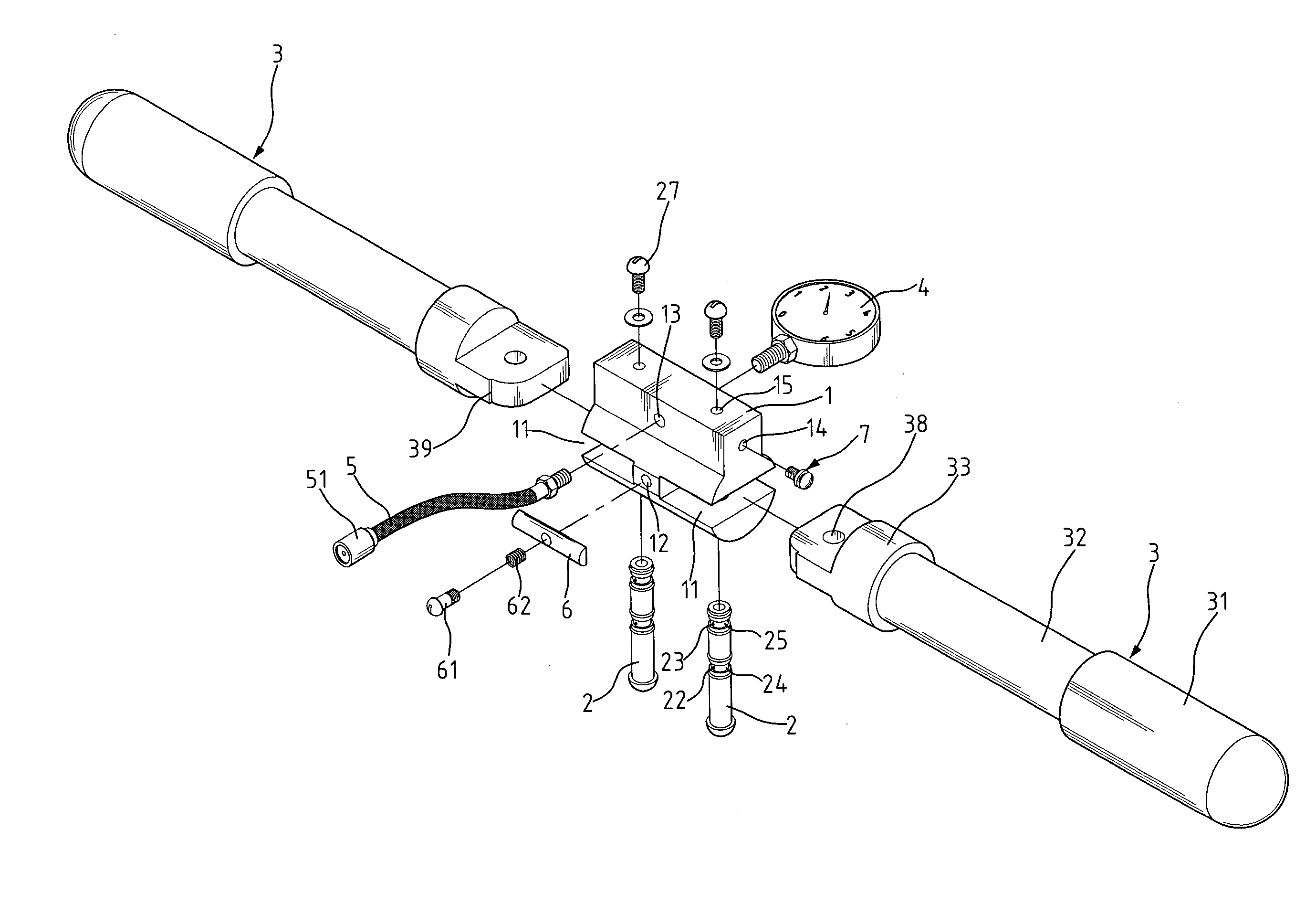
Figure 1 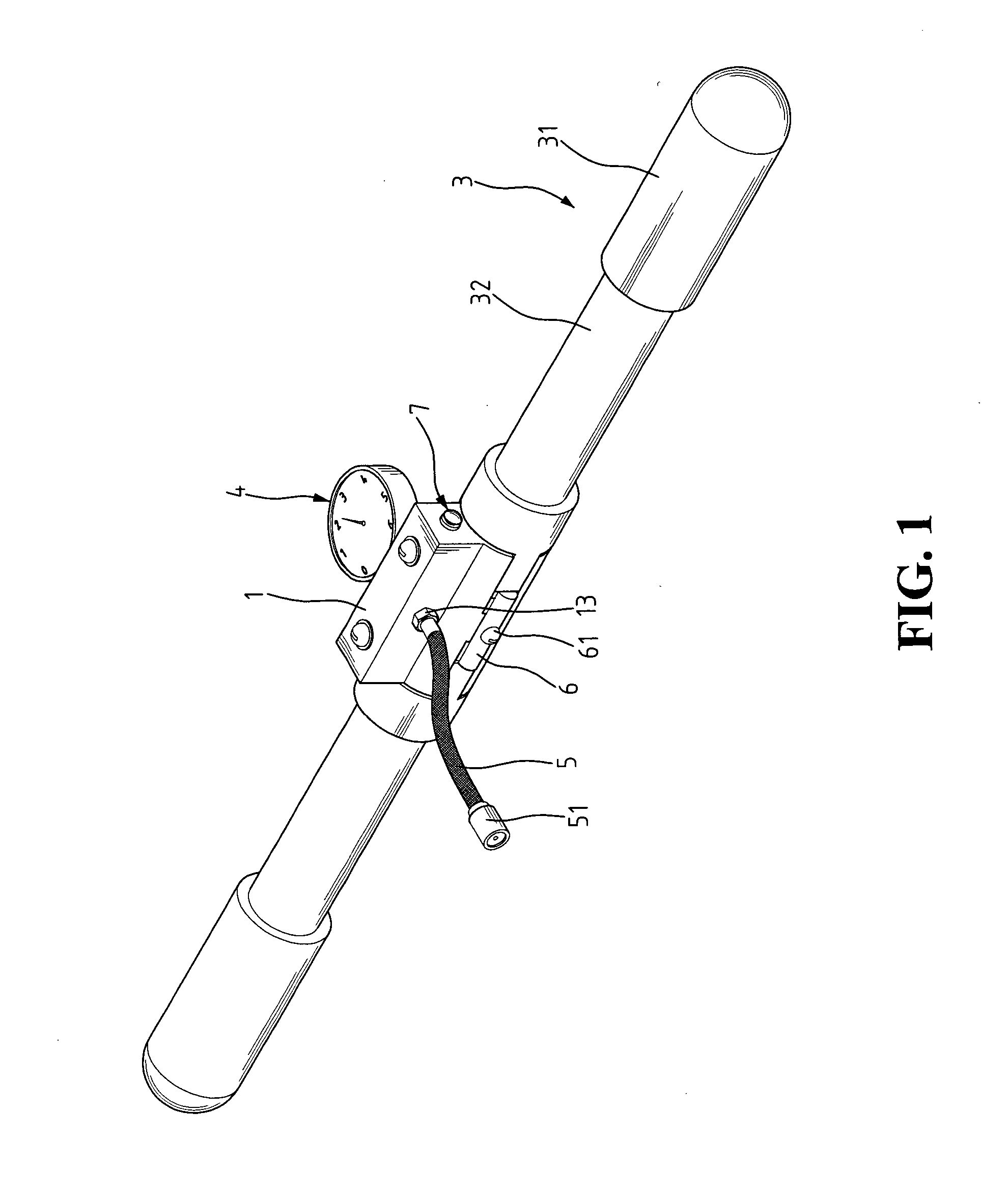
Figure 2 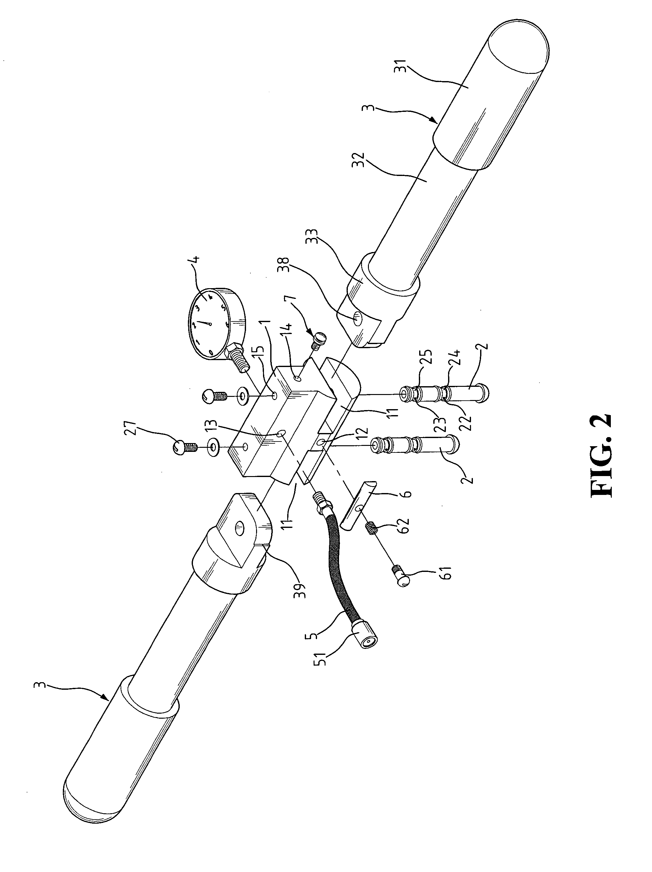
Figure 3
Abstract
Description
BACKGROUND OF THE INVENTION
[0001] 1. Field of the Invention
[0002] The present invention relates to a hand-operated inflator, and in particular to an inflator having dual cylinder design, so that an object can be inflated at a faster rate using less effort.
[0003] 2. The Related Art
[0004] Generally, an air pump or hand-operated inflator is used to inflate tires, balloons, inflatable toys or other inflatable objects. Commonly seen hand-operated inflators have one air cylinder. The refilling of an inflatable object may take a long time and is not an easy task for ordinary users.
[0005] A recent design of the inflator employs two air cylinders, which is comprised of a base block and two cylinders coupled on two sides of the base block. The dual-cylinder inflator is attached with a discharge tube that has a mouthpiece on the other end for fitting on to the air nozzle of an inflatable object.
[0006] The dual-cylinder design is intended to expedite the refilling operation. The inflator ...
Examples
Embodiment Construction
[0028] A hand-operated inflator constructed in accordance with an preferred embodiment of the present invention as shown in FIGS. 1 and 2, comprises a central block 1, two pivot pins 2, and two cylinders 3 each having a free end forming a handle 31. The central block 1 has a discharge tube 5 attached to a central outlet 13 on the back surface, an pressure meter 4 mounted at the center point on the front surface, an over pressure value 7 received on one side, and two slots 11 formed on the lower portion of each side. The two cylinders 3 each having a protruded portion on one end are fitted into the slots 11 and rotatably connected by pivot pins 2.
[0029] In the air refilling process, the user can monitor the actual pressure inside the object through the pressure meter 4 as the object is being refilled. If the pressure inside the object gets excessively high, air pressure can be released by the over pressure valve 4 until the preset pressure is reached.
[0030] The inflator also has a ...